Controlling the system time clock of an MPEG decoder

a technology of mpeg decoder and system time clock, which is applied in the field of control of system time clock of mpeg decoder, can solve problems such as lip synchronization, erroneous dts or pts, and may occur, and achieve the effect of improving the accuracy of stc value and simplifying the configuration

Inactive Publication Date: 2005-11-29
ABOV SEMICON
View PDF14 Cites 26 Cited by
  • Summary
  • Abstract
  • Description
  • Claims
  • Application Information

AI Technical Summary

Benefits of technology

[0025]The present invention provides a method and device for controlling an STC of an MPEG decoder, which simplifies a configuration for management and correction of an STC value and improves accuracy of the STC value.

Problems solved by technology

Here, problems related to lip synchronization occurs when processing and outputting audio and video data.
However, if a clock signal of 27-MHz used in the decoder is not accurately synchronized with the clock signal in the encoder, problems may occur.
For example, if the actual decoder clock frequency is a little slower than an ideal clock frequency of 27-MHz, a buffer empty state may be erroneously achieved when the DTS or PTS detected in the decoder is compared with the STC value, and found to be greater than the acceptable error range, resulting in the erroneous skipping of the DTS or PTS.
Conversely, the DTS or PTS compared with the STC may be found to be smaller than the acceptable error range if the actual decoder clock frequency is a little faster than an ideal clock frequency of 27-MHz, and a buffer full state may be erroneously achieved.
The related art clock recovery system of the MPEG-2 decoder suffers from another problem.
This increases the overall complexity and cost of hardware components.

Method used


Image

  • Controlling the system time clock of an MPEG decoder
  • Controlling the system time clock of an MPEG decoder
  • Controlling the system time clock of an MPEG decoder

Examples


first embodiment

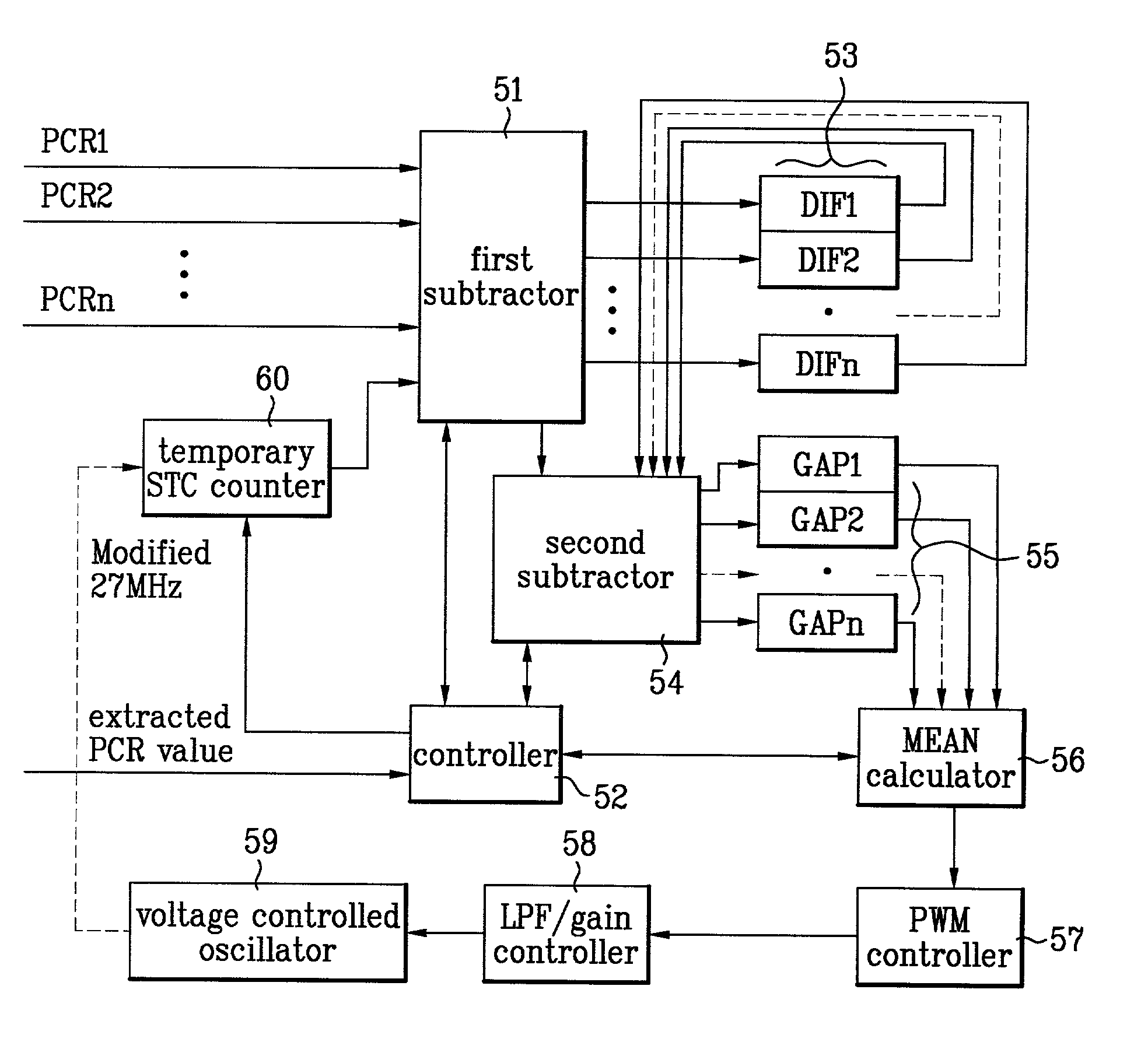
[0041]A device for controlling a system time clock (STC) according to the present invention will be described with reference to FIGS. 5 and 6.

[0042]The first embodiment of the present invention includes a first subtractor 51 for receiving an n number of PCR values (PCR1, PCR2, . . . , PCRn) and receiving an STC value, and outputting a gap value (i.e., the difference between a PCR value and a STC value), a controller 52 for determining whether the current PCR value has been updated two or more times, an n number of DIF registers 53 for storing the gap value of the first subtractor if the PCR value has not been updated two or more times under the control of the controller 52, a second subtractor 54 for calculating a gap value between the output value of the first subtractor 51 and the value stored in the n number of DIF registers 53 if the PCR value has been updated two or more times, an n number of gap registers 55 for storing the resultant value of the second subtractor 54, and a me...

second embodiment

[0051]The device and method for controlling the STC according to the present invention will be described with reference to FIGS. 7 and 8.

[0052]In this second embodiment, the STC is controlled by using an interrupt control function based on the MCU without using a subtractor. The device for controlling the STC according to the second embodiment of the present invention also includes an n number of temporary STC registers for storing temporary STC values.

[0053]As shown in FIG. 7, the device for controlling the STC according to the second embodiment of the present invention includes an n number of PCR registers 72 for temporarily storing an n number of PCR values (PCR1, PCR2, . . . , PCRn); a temporary STC counter 71 for counting an STC value increased to 27-MHz; a temporary STC register 74 for temporarily storing an n number of temporary STC counter values (Temp—STC1, Temp—STC2, . . . , Temp—STCn) counted by the temporary STC counter 71; an MCU 73 for calculating a gap value between t...


PUM


Abstract

During decoding and processing of program clock reference (PCR) values in MPEG-2 transport streams, a first initial difference value is obtained by calculating a difference between a first detected PCR value and a system time clock (STC) value generated when the first PCR value is detected. Depending on the update status of the PCR values, a second initial difference value is obtained by calculating a difference between a second detected PCR value and a STC value generated when the second PCR value is detected. Thereafter, a composite difference value is obtained by further calculating a difference between the first initial difference value and the second initial difference value. Subsequently, the first and second initial difference values, and the composite difference values are calculated for a predetermined number of detected PCR values so that the decoder clock signal is generated and maintained at approximately the same frequency as an encoder clock signal.

Description

BACKGROUND OF THE INVENTION[0001]1. Field of the Invention[0002]The present invention relates to Moving Picture Expert Group-2 (MPEG-2) technology, and more particularly, to a method and device for controlling a System Time Clock (STC) of an MPEG decoder, in which the STC being used as a standard for synchronization during multi-decoding is effectively controlled.[0003]2. Background of the Related Art[0004]Generally, digital video technology is used in various fields, such as computers and home appliances, as well as in communications technology, such as video conferencing and video telephones. Particularly, various apparatuses for recording and reproducing digital video signals, such as digital video cassette recorders and digital video cassettes, adopt MPEG standards of media (such as MPEG-2) for storing digital video signals.[0005]The MPEG standards provide for the transmission of digital information by dividing digital data into packets forming data bit streams, which are multip...

Claims


Application Information

Patent Timeline
Patent Type & Authority Patents(United States)
IPC IPC(8): G06T9/00H04N5/04H04N5/12H04N5/44H04N21/43
CPCG06T9/007H04N5/04H04N21/4305H04N5/126H04N5/4401H04N21/426H04N21/485
Inventor MIN, KYUNG PA
Owner ABOV SEMICON
Why Eureka
Try Eureka