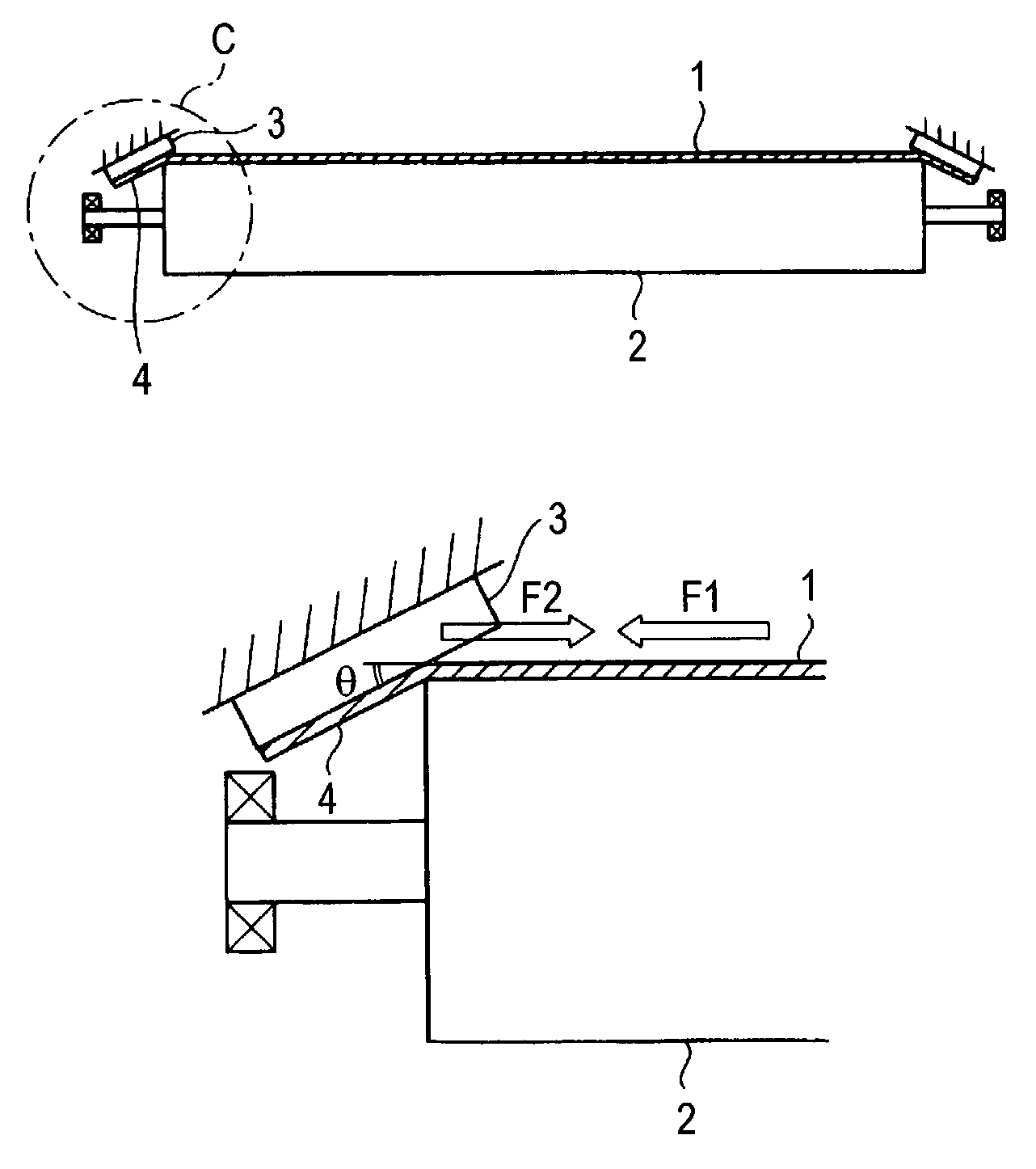
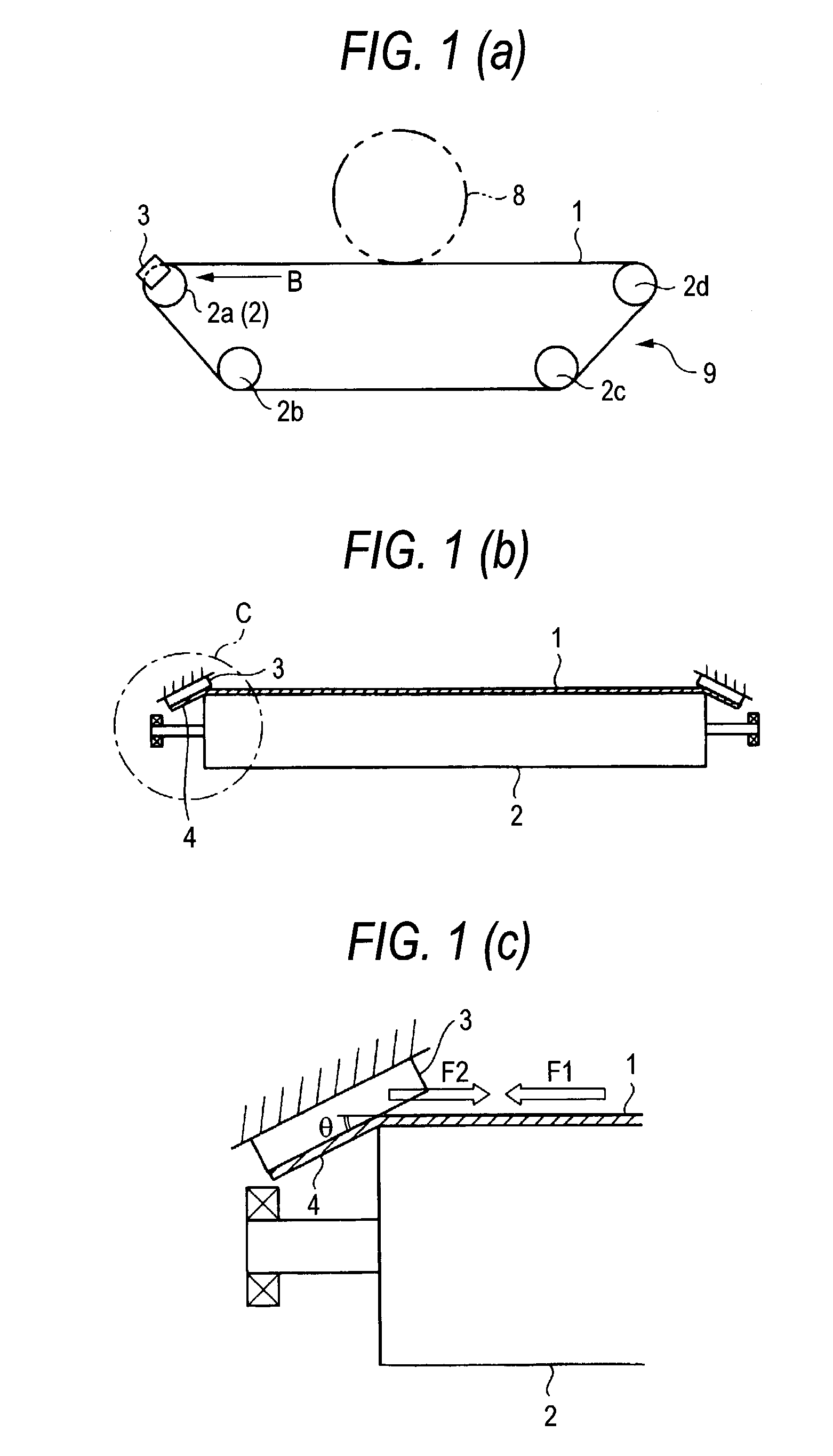
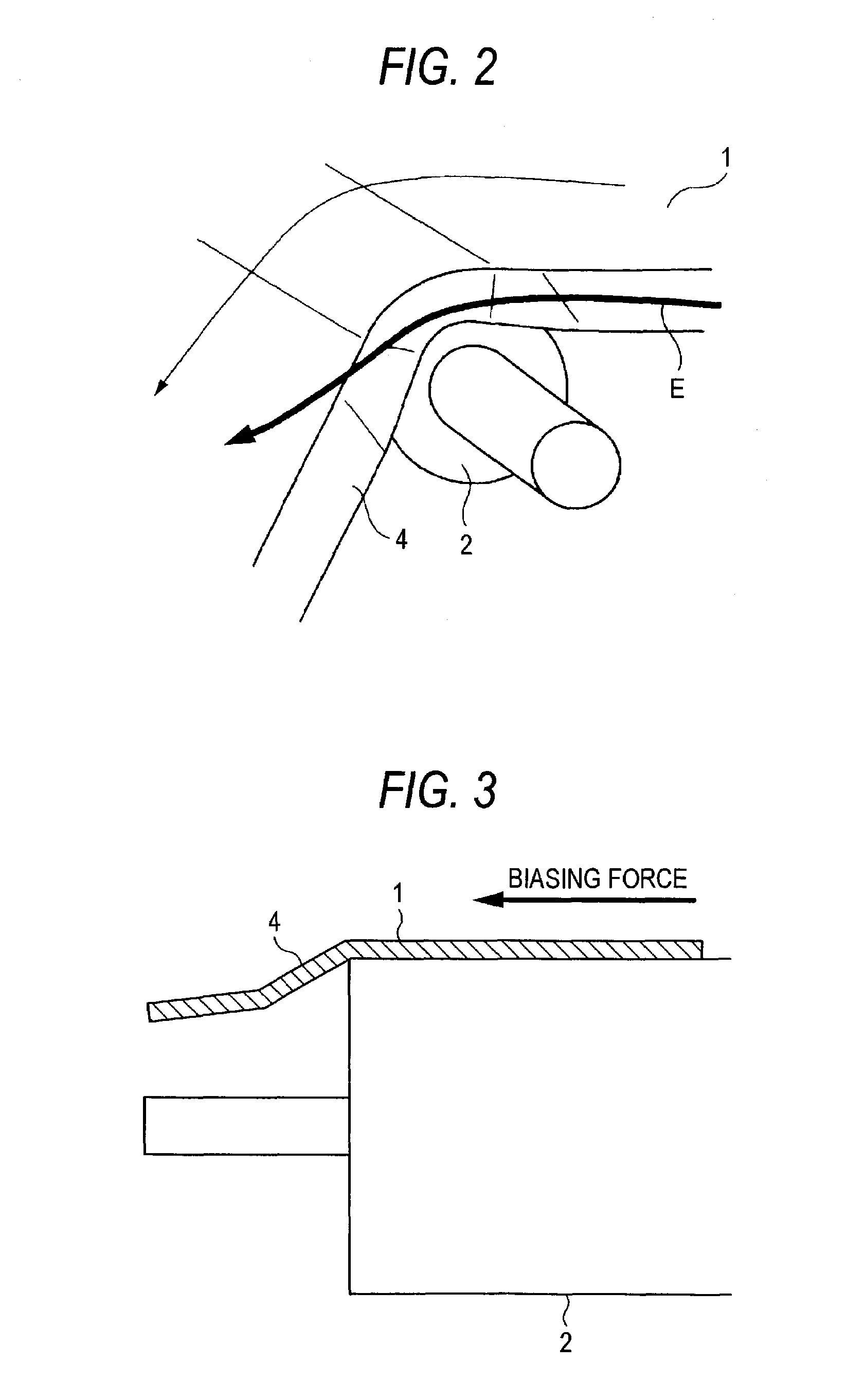
Belt transporting device and image forming apparatus using the same

a technology of image forming apparatus and transporting device, which is applied in the direction of electrographic process, instruments, gearing, etc., can solve the problems of belt damage, rib root peeled off, and rib root cracked, so as to prevent belt biasing and damage, simple construction, and avoid secondary troubles of belt meandering and the like

Inactive Publication Date: 2005-11-29
FUJIFILM BUSINESS INNOVATION CORP
View PDF12 Cites 51 Cited by
  • Summary
  • Abstract
  • Description
  • Claims
  • Application Information

AI Technical Summary

Benefits of technology

[0023]It is an objective of the present invention to provide a belt transporting device in which no stress is generated when the biasing of the belt is regulated, and with an extremely simple construction, the belt biasing and damaging are prevented, and the secondary troubles of belt meandering and the like is effectively avoided.

Problems solved by technology

The root of the rib will be cracked, and in an extreme case, the rib root is peeled off and the belt is seriously damaged.
In this state, non-uniformity of rib bonding accuracy will cause undulation and tilting in the running belt, so that the running belt will meander.
As a result, a color picture finally formed on the recording medium suffers from image defects, such as color misregistration and hue variation.
The work of joining (bonding) of the ribs is troublesome, from the very beginning.
The rib bonding leads to cost increase, however, and in this respect, it is not a desirable measure.
The undulation will crack the belt end, and in an extreme case, the belt is broken.
Even in a case where no undulation occurs, the flange frictionally slides on the side face of the belt end continuously, wear grows and hence, the durability performance is deteriorated.
This technique is still unsatisfactory in solving the belt biasing problem since is complicated in construction and high in cost.
While a chance of the belt cracking and damaging owing to the contact of the belt with the flange or ribs is lessened, indeed, the possibility that the belt is undulated by the end of the roll, and cracked and damaged is still present.
This technique also requires certain accuracy for the placement of the tapered roll, and is complicated in construction.
A possibility that the undulation, cracking and damaging of the belt occurs in a gap part between the tension roll and the tapered roll is present.
As described above, the conventional belt-biasing preventing techniques still have technical problems to be solved: at the contact part of the belt where it contacts with the regulating member, such as the flange or the ribs, the end part of the auxiliary roll, and the gap, the stress generated therein by the biasing force give rise to the undulation, meandering, cracking, damaging of the belt.
In the case additionally using the auxiliary roll, the construction is further complicated, and disadvantageous also in the light of cost.

Method used


Image

  • Belt transporting device and image forming apparatus using the same
  • Belt transporting device and image forming apparatus using the same
  • Belt transporting device and image forming apparatus using the same

Examples


embodiment 1

[0077]FIG. 4 is a diagram schematically showing an image forming apparatus incorporating the present invention thereinto.

[0078]In the figure, the image forming apparatus includes a photo-receptor drum 10 and an intermediate transfer belt 20 which comes in contact with the photo-receptor drum 10 over a fixed area in a state that it extends along the shape of the photo-receptor drum 10, and receives a toner image from the photo-receptor drum 10.

[0079]In the instant embodiment, the photo-receptor drum 10 includes a photosensitive layer of which resistance reduces under illumination of light. Disposed around the photo-receptor drum 10 are a charger unit 11 for charging the photo-receptor drum 10, an exposure unit 12 for writing electrostatic latent images of respective colors (black, yellow, magenta, and cyan in the embodiment) onto the charged photo-receptor drum 10, a rotary developing unit 13 for developing the color latent images on the photo-receptor drum 10 into color toner images...

embodiment 2

[0121]FIGS. 6(a) and 6(b) show a key portion of a belt transporting device (a belt unit having an intermediate transfer belt 20 assembled thereinto) in an

[0122]In the figure, the belt transporting device, as in the embodiment 1, includes a guide member 50 located near a tension roll 22, but a construction of the guide member 50 is different from that in the embodiment 1.

[0123]The guide member 50 of the instant embodiment, as shown in FIGS. 6(a) and 6(b), includes a guide block 51 disposed at a part opposed to the central part of a winding area “m” of the tension roll 22. The guide block 51 includes an arcuate guide face 52 to be abutted on a belt-end edge part 20a.

[0124]Attention is paid to the intermediate transfer belt 20 passing the tension roll 22 in the instant embodiment. At each of the entrance and exit of the belt 1 winding area “m” of the tension roll 22, a pressure by the tension caused by the belt-end edge part 20a is large, and the belt-end edge part 20a is greatly bent...

embodiment 3

[0126]FIG. 7 shows a key portion of a belt transporting device (a belt unit having an intermediate transfer belt 20 assembled thereinto) in an

[0127]In the figure, the belt transporting device, as in the embodiments 1 and 2, includes a guide member 50 located near a tension roll 22, but a construction of the guide member 50 is different from that in the embodiments 1 and 2.

[0128]The guide member 50 of the instant embodiment rotatably supports a guide roll 57 on a bracket 56. A belt-end edge part 20a protruded from one end of the tension roll 22 is brought into sliding contact with the rotational periphery surface of the guide roll 57 to regulate the bending.

[0129]In the embodiment, sliding resistance between the guide member 50 and the belt-end edge part 20a is extremely small in value. The running of the intermediate transfer belt 20 is not impeded by friction resistance associated with the guide member 50.

[0130]As seen from the foregoing description, in the invention, the guide mem...


PUM


Abstract

A belt transporting device for circulatingly transporting an endless belt, which is in use with an image forming apparatus, such as copying machine or a printer. The belt transporting device includes a plurality of tension rolls, an endless belt laid on the tension rolls, the endless belt having a belt-end edge part protruding from an end of one of the tension roll and a guide member provided in the vicinity of the endless belt. The guide member comes in contact with the belt-end edge part so as to bend the belt-end edge part in a tapering-off direction. The guide member regulates the shape of the belt-end edge part so that a rotary peripheral length of the belt-end edge part becomes smaller than that of an area where a rear side of the endless belt is in contact with the tension roll.

Description

BACKGROUND OF THE INVENTION[0001]1. Field of the Invention[0002]The present invention relates to a belt transporting device for circulatingly transporting an endless belt, which is in use with an image forming apparatus, such as copying machine or a printer. More particularly, the invention relates to a belt transporting device which is effective in preventing an inclination of the belt and an image forming apparatus using the same.[0003]2. Background Art[0004]Recently, in the image forming apparatus based on the electrophotography, for example, demands for size reduction, picture quality improvement, and cost reduction are increasing. To satisfy the demands, it is effective to employ the belt unit in the intermediate transfer body, sheet conveying body, fixing unit and the like.[0005]In the intermediate transfer type image forming apparatus based on the electrophotography system, for example, which is already proposed, toner images of respective colors are successively formed on a ...

Claims


Application Information

Patent Timeline
Patent Type & Authority Patents(United States)
IPC IPC(8): G03G15/00B65H5/02G03G15/16
CPCG03G15/1605G03G2215/00151G03G15/1615
Inventor SATO, MASAHIROKITAMURA, ATSUYUKIKURAMOTO, SHINICHISUZUKI, WATARUWATANABE, KOICHINISHIDE, SHUICHIYAMAMOTO, MITUO
Owner FUJIFILM BUSINESS INNOVATION CORP
Why Eureka
Try Eureka