
Method of tank leak diagnosis

a technology of leak detection and tank, which is applied in the direction of fluid tightness measurement, combustion air/fuel air treatment, instruments, etc., can solve the problems of gas intermediate storage, difficult and expensive gas storage, and negative pressure produced after the turning off of the internal combustion engin

Inactive Publication Date: 2005-11-29
ROBERT BOSCH GMBH
View PDF2 Cites 59 Cited by
  • Summary
  • Abstract
  • Description
  • Claims
  • Application Information

AI Technical Summary

Benefits of technology

[0004]Accordingly, it is an object of the present invention to provide a method of tank leak diagnosis, which avoids the disadvantages of the prior art.

Problems solved by technology

A leak in the fuel tank is recognized by a pressure increase in the fuel tank, which is caused by the leak.
This method however has the disadvantage in that the negative pressure is produced after the turning off of the internal combustion engine, since the gas which is aspirated from the tank ventilating device can no longer be supplied for combustion in the internal combustion engine.
Instead, the gas must be intermediately stored in an additional storage which is quite complicated and expensive and not discharged into the atmosphere.
Moreover, it is also disadvantageous that the negative pressure is produced by an additional pump.
This method has the disadvantage that a storage which receives the evaporated fuel can not be rinsed to a full degree, when the storage is held approximately during the whole operation of the internal combustion engine under a predetermined negative pressure.

Method used


Image

  • Method of tank leak diagnosis
  • Method of tank leak diagnosis
  • Method of tank leak diagnosis

Examples


Embodiment Construction

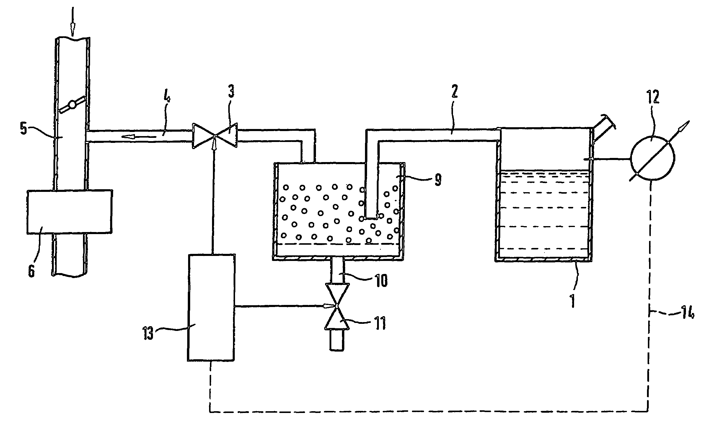
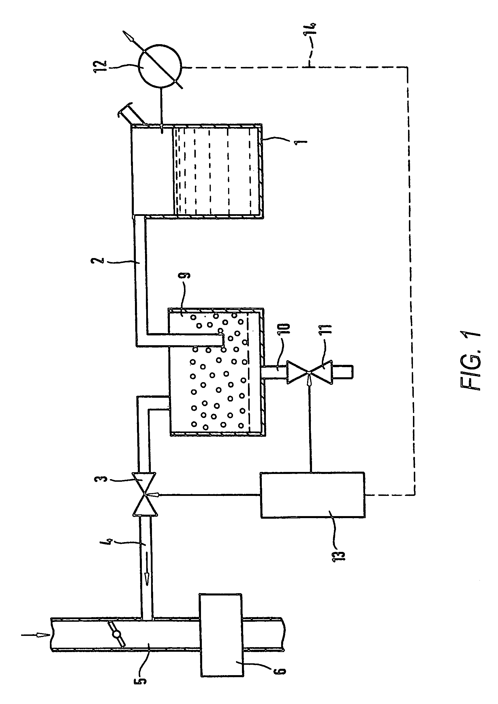
[0019]A known tank ventilation device is shown in a simplified way in the drawing. The tank ventilation device operates for supplying an evaporated fuel from a fuel tank to an internal combustion engine. A fuel tank 1 is connected through a ventilation conduit 2, a tank ventilation valve 3 and a suction conduit 4 at least indirectly with a so-called suction pipe 5 of an internal combustion engine 6. For example one storage 9 can be arranged in the ventilation conduit 2. In a known manner it takes preliminarily the fuel evaporated from the fuel tank 1. The storage 9 contains a material which absorbs the fuel, for example activated coal. The storage 9 is connected through an aeration conduit 10 with atmosphere. The aeration conduit 10 has a flow element 11 formed for example as a check valve.

[0020]A pressure sensor 12 measures a pressure in the fuel tank 1 and supplies a signal through a signal conductor 14 to an electronic motor control 13. The pressure sensor 12 is for example a dif...


PUM


Abstract

A method of tank leak diagnosis in a tank ventilation device including a fuel tank which is connected at least indirectly through a storage and tank ventilation valve with a suction pipe of an internal combustion engine of the vehicle, with the storage having an aeration conduit with a check valve, includes performing a tank leak diagnosis by a negative pressure after turning off of the internal combustion engine; and producing the negative pressure in the fuel tank immediately before the turning off of the internal combustion engine.

Description

BACKGROUND OF THE INVENTION[0001]The present invention generally relates to a method for tank leak diagnosis.[0002]One of such methods for a tank leak diagnosis is disclosed for example in U.S. patent document 2002 / 0139173A1. The tank leak diagnosis in accordance with this method is performed after turning off of an internal combustion engine. A pump, after turning off of the internal combustion engine, generates a negative pressure in the fuel tank. A leak in the fuel tank is recognized by a pressure increase in the fuel tank, which is caused by the leak. This method however has the disadvantage in that the negative pressure is produced after the turning off of the internal combustion engine, since the gas which is aspirated from the tank ventilating device can no longer be supplied for combustion in the internal combustion engine. Instead, the gas must be intermediately stored in an additional storage which is quite complicated and expensive and not discharged into the atmosphere....

Claims


Application Information

Patent Timeline
IPC IPC(8): B60K15/035F02M25/08F02M33/02G01M3/04G01M3/08G01M3/32G01M17/00G06F19/00
CPCF02M25/0809
Inventor LEDERLE, KARL-BERNHARDPFEIL, MICHAELPERROT, NICOLAS
Owner ROBERT BOSCH GMBH
Features
  • Generate Ideas
  • Intellectual Property
  • Life Sciences
  • Materials
  • Tech Scout
  • Unparalleled Data Quality
  • Higher Quality Content
  • 60% Fewer Hallucinations
Learn More