Method of manufacturing winding of rotary electric machine

a technology of rotary electric machines and windings, which is applied in the direction of manufacturing tools, magnets, magnetic bodies, etc., can solve the problems of difficulty in maintaining electrical insulation between stator cores and electric conductors

Active Publication Date: 2005-12-06
DENSO CORP
View PDF16 Cites 24 Cited by
  • Summary
  • Abstract
  • Description
  • Claims
  • Application Information

AI Technical Summary

Benefits of technology

[0011]Because deformation of the corner of the electric conductor is restricted by the corner portion of the die, it is l...

Problems solved by technology

Accordingly, it is difficult to maintain electrical in...

Method used


Image

  • Method of manufacturing winding of rotary electric machine
  • Method of manufacturing winding of rotary electric machine
  • Method of manufacturing winding of rotary electric machine

Examples


Embodiment Construction

[0025]Embodiments of the present invention will be described hereinafter with reference to drawings.

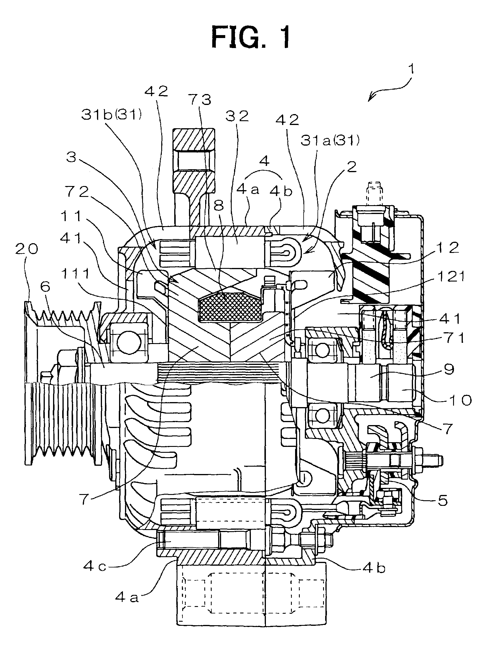
[0026]As shown in FIG. 1, a vehicular alternator 1 of the embodiment includes a stator 2, a rotor 3, a housing 4, a rectifier 5 and the like.

[0027]The rotor 3, which functions as a field magnet, rotates with a shaft 6, and includes a Lundell-type pole core 7, a field coil 8, slip rings 9, 10, a mixed flow fan 11, and a centrifugal fan 12 as an air blowing device. The shaft 6 is connected to a pulley 20, and rotated by an onboard engine (not shown) for driving a vehicle.

[0028]The Lundell-type pole core 7 is constructed of a pair of pole cores. The Lundell-type pole core 7 includes a boss portion 71, which is fixed to the shaft 6, disc portions 72, which extend from the ends of the boss portion 71 in the radial direction, and twelve claw poles 73.

[0029]The mixed flow fan 11 adjacent to the pulley 20 includes blades that are arranged at acute angles and blades that are arranged at right ...


PUM

PropertyMeasurementUnit
aaaaaaaaaa

Abstract

A method of manufacturing a winding of a rotary electric machine includes steps of pressing a portion of a conductor segment in a predetermined direction to reduce its dimension in the direction, inserting the conductor segment into a slot of a stator core, bending the conductor segments and joining ends of the conductor segments. In the pressing step, the conductor segment is pressed with a punch in a condition that it is held in a die that has curved inside corner portions to restrict deformation of corners of the pressed portion.

Description

CROSS REFERENCE TO RELATED APPLICATION[0001]This application is based on Japanese Patent Applications No. 2002-55781 filed on Mar. 1, 2002 and No. 2003-11912 filed on Jan. 21, 2003, the disclosure of which are incorporated herein by reference.FIELD OF THE INVENTION[0002]The present invention relates to a method of manufacturing a winding of a rotary electric machine, such as a vehicular alternator mounted on passenger vehicles or trucks and a method of forming a dent on the winding.BACKGROUND OF THE INVENTION[0003]In recent years, an improvement of a power generation performance is more required in a vehicular alternator, in accordance with an increase in current consumer by safety control apparatus. In a vehicular alternator disclosed in JP-A-2000-166148, for example, U-shaped electric conductors are regularly arranged in slots of a stator core. Occupancy of electric conductors in the slots is increased, thereby improving power output.[0004]In this alternator, gaps are defined betw...

Claims


Application Information

Patent Timeline
IPC IPC(8): H02K3/38H02K3/50H02K15/04H02K3/04H02K19/22
CPCH02K15/0414H02K15/0421Y10T29/49073Y10T29/49009Y10T29/53157Y10T29/53148Y10T29/49151
Inventor TOKIZAWA, TAKASHIKATO, MITSURUNAKAMURA, YOSHINORIKITAKADO, YASUNORIMURAHASHI, MOTOHIRO
Owner DENSO CORP
Why Eureka
Try Eureka