Syringe device with resistive ridges and methods of use

a ridge and syringe technology, applied in the field of syringes with resistive ridges, can solve the problems of no mechanism to ensure that such a medicament is substantially dissolved and dispensed

Inactive Publication Date: 2005-12-06
G6 SCI CORP
View PDF26 Cites 32 Cited by
  • Summary
  • Abstract
  • Description
  • Claims
  • Application Information

AI Technical Summary

Benefits of technology

[0017]The present invention is a syringe in which one or more ridges are formed within the barrel of the syringe or along the plunger stem of the syringe device to provide tactile or sensory feedback in the form of resistive changes. The tactile feedback is useful to humans who are, for example, visually impaired, rushed, or in low lighting situations. The sensory feedback is also useful to machinery in automated operations.
[0018]“Ridge” as used herein means a protrusion or indentation formed within the barrel of a syringe or along the plunger stem of a syringe device. A ridge as used herein may be of desired size, shape, dimension, elasticity, and number so as to provide tactile or sensory feedback, typically in the form of a resistive change to axial movement of the gasket within the barrel. Tactile feedback may be sensed by a user or via a machine interface and provide indication of gasket position and / or speed and / or displacement, for example. Accordingly, a ridge may be substantially tactile, provide strong resistance to provide a stopping or holding action, provide substantially the same or different amounts of resistance depending on the direction of axial movement, be designed for one time use, be formed in a pattern to provide additional indication of position or speed, or otherwise be exploited to advantage.

Problems solved by technology

Vetter provides for a bypass passage forward of the plunger which may for example, hold a soluble medicament, but provides no mechanism to ensure that such a medicament is substantially dissolved and dispensed.

Method used


Image

  • Syringe device with resistive ridges and methods of use
  • Syringe device with resistive ridges and methods of use
  • Syringe device with resistive ridges and methods of use

Examples


Embodiment Construction

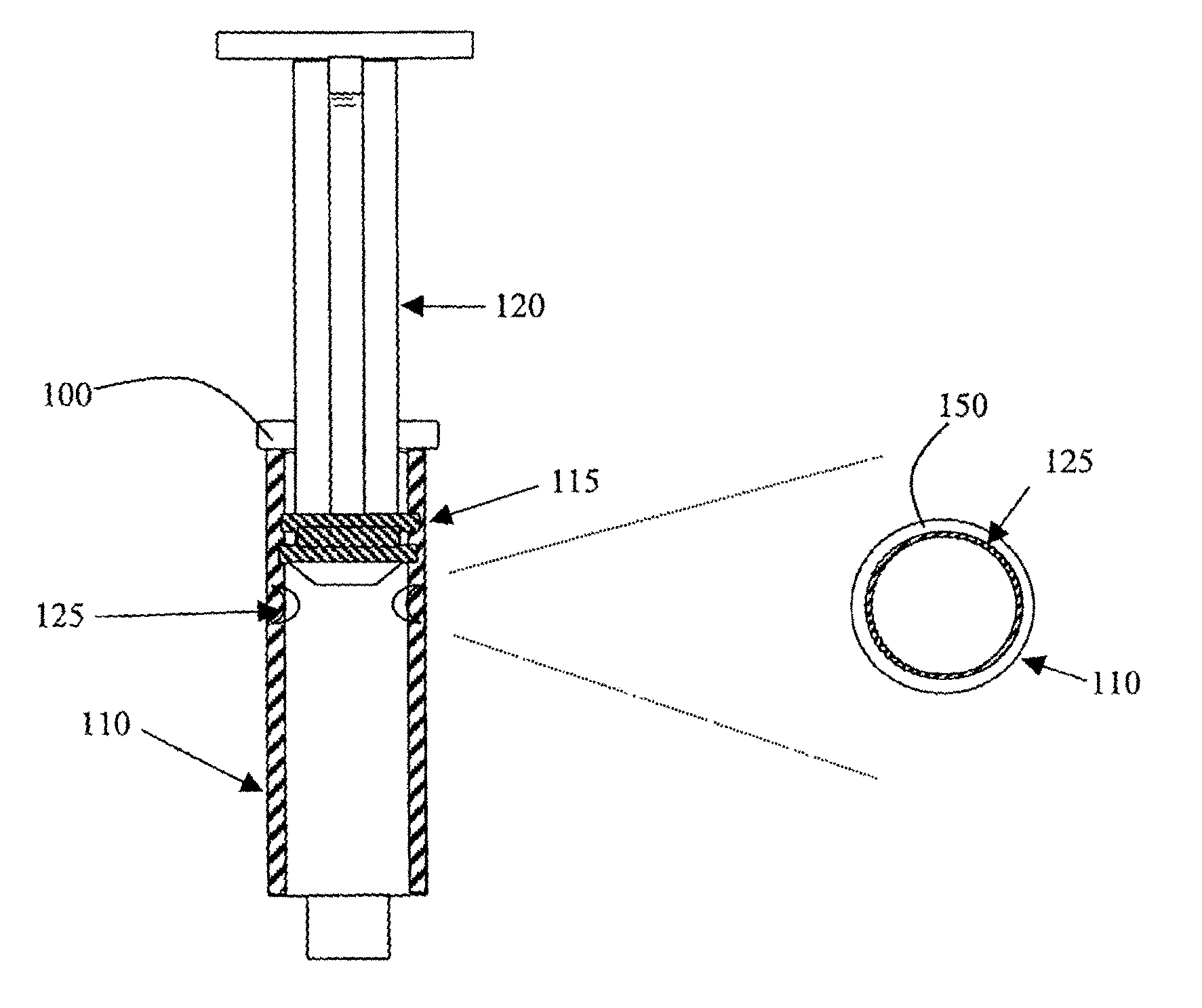
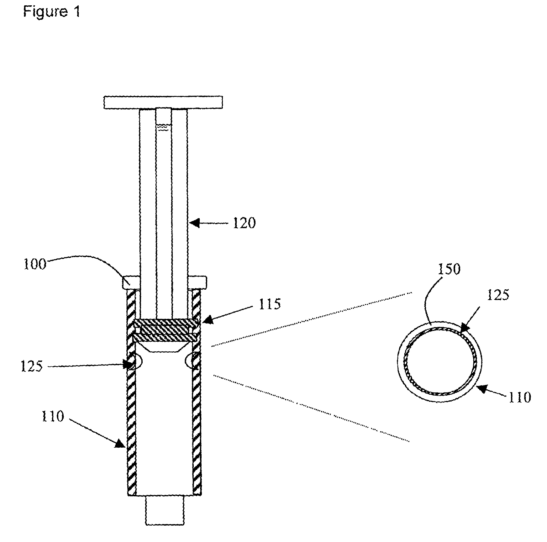
[0024]FIG. 1 shows syringe device 100 of the present invention having a cylindrical tube or barrel 110 with plunger 120 and ribbed gasket 115 attached to the plunger 120. A novel, tactile ridge 125 has been implemented within the barrel 110. (Please note that the ridge 125 is illustrated in FIG. 1, as are all of the ridges illustrated in subsequent figures, in exaggerated size for clarity. The actual size and shape of a particular ridge depends on the use of the device.) The tactile ridge 125 is further shown in expanded cross-section as a protruding ring within the barrel 110. The tactile ridge 125 is implemented so as to provide a slight, incremental resistance that may be physically sensed as the gasket 110 is caused to move over the tactile ridge. As shown in expanded view in FIG. 1, the tactile ridge 125 in this instance is formed as an internal ring. As will be described further, protrusions such as bumps or indentations formed within the syringe barrel may also be used to pro...


PUM


Abstract

A syringe device incorporating ridges that cause resistive changes to the movement of the syringe gasket or plunger, thereby providing user feedback as to the position and speed of plunger movement. Such user feedback may be useful in stressful situations, under poor lighting conditions or in other unfavorable circumstances. Additionally, in certain embodiments these ridges may aid in accurate dispension or allow the syringe to derive additional functionality, such as performing as a vacuum source. Ridges can be protrusions such as tabs, bubbles or continuous rings for single or repeated use or these ridges may be formed as indentations. Ridges may be formed in patterns, in various sizes and shapes or these ridges may be mixed and matched as required or desired. Ridges may also be formed from a soluble material and the resistive change may itself provide indication that the material has been substantially dissolved and dispensed. In some embodiments these ridges are formed primarily within the barrel portion of the syringe. In other embodiments these ridges may be formed on the plunger stem of the syringe. Ridges may be constructed to provide one type of resistive change during the aspiration stroke and a different resistive change to motion in the opposite direction.

Description

BACKGROUND OF THE INVENTION[0001]The present invention relates generally to a hypodermic syringe and more particularly to a syringe device having at least one ridge within the barrel portion of the syringe or along the plunger stem of the syringe device.[0002]Syringe devices may be designed or intended for single or repeated use and may be operated manually or all or a portion of their operation may be mechanized. In general, a syringe device is comprised of three basic components: a barrel, which is typically cylindrical, a plunger, and a gasket which is affixed to the plunger so as to move in conjunction with the plunger. The gasket is typically designed to substantially seal within the barrel such that during operation the units function as a displacement piston. As such, this piston configuration provides for two directions of axial movement which may generally be termed an aspiration cycle and a dispensing cycle. Needles, filters, drive mechanism, locks, and protectors, as well...

Claims


Application Information

Patent Timeline
Patent Type & Authority Patents(United States)
IPC IPC(8): A61M5/31A61M5/315
CPCA61M5/3129A61M2005/31506A61M2205/582
Inventor FERGUSON, GARY WILLIAM
Owner G6 SCI CORP
Why Eureka
Try Eureka