
Automatic focusing device and the electronic image pickup apparatus using the same

a technology of automatic focusing and electronic image pickup, which is applied in the direction of camera focusing arrangement, printers, instruments, etc., can solve the problems of low detection accuracy of focusing position, and inability to detect the state of focusing in time, so as to facilitate continuous image picking

Inactive Publication Date: 2005-12-06
FUJI ELECTRIC CO LTD
View PDF15 Cites 49 Cited by
  • Summary
  • Abstract
  • Description
  • Claims
  • Application Information

AI Technical Summary

Benefits of technology

[0021]The auto-focusing device according to the invention shifts the focusing lens to the accurate focusing position thereof by the TTL focus detecting means and corrects, if necessary, the conversion reference automatically, based on the shift length of the focusing lens and the distance of the object measured by the open-control range finding means, in order to always keep an accurate conversion reference. Since the distance of the object measured by the open-control range finding means is converted to the focusing position of the focusing lens, the focusing lens is always positioned at the correct focusing position. Therefore, even the open-control range finding means makes the image pickup lens form a well focused image of the object.
[0024]Advantageously, the image pickup lens includes zoom lenses, and the conversion reference is corrected one or more times when the zooming ratio of the image pickup lens exceeds a predetermined range. The present inventor has found it necessary to correct the conversion reference when the zooming ratio is changed. By correcting the conversion reference when the zooming ratio is changed, the open-control range finding means facilitates focusing the image of the object quickly and accurately even when the image pickup lens executes high-ratio zooming.
[0026]The present inventor has found it is necessary to correct the conversion reference when a large temperature change occurs. By correcting the conversion reference when a large temperature change occurs, the open-control range finding means facilitates focusing the image of the object quickly and accurately even when a large environmental change is caused.
[0028]Advantageously, the image pickup lens is exchangeable, and the conversion reference is corrected one or more times when image pickup lens is changed to another one. The present inventor has found it is necessary to correct the conversion reference every time when the image pickup lens is exchanged to another one. By correcting the conversion reference when the image pickup lens is changed to another one, the open-control range finding means facilitates focusing the image of the object quickly and accurately corresponding to the new image pickup lens.
[0030]The present inventor has found it is necessary to correct the conversion reference every time when the image of the object is picked up when the release switch is pressed. The electronic image pickup apparatus corrects the conversion reference when the release switch is pressed halfway and picks up the image of the object focused quickly and accurately by the open-control range finding means. The electronic image pickup apparatus facilitates continuous pick up of the image of the object.

Problems solved by technology

Since it is necessary to compare a great deal of data, it takes time to detect the state of focusing especially when the image pickup lenses are far from the focusing position at the start.
Since it is necessary to drive the CCD image pickup devices repeatedly, high current consumption is caused, and, therefore, the battery is consumed soon.
Although sufficient brightness is obtained by a flash light during the image pickup operation, the insufficient sensitivity of the pixel causes low detection accuracy of the focusing position in the dark circumstances, since the flash light is not irradiated during the focusing operation.
As described above, the shortcomings of the TTL focus detecting means more adversely impact the ability to obtain a higher image quality by minimizing the CCD image pickup devices, to increasing the zooming ratio of the image pickup lens, and to reduce power consumption.
Since the open-control range finding means executes an open control to detect the focusing point, the open-control range finding means is not employable to the auto-focusing device when the focusing position of the image pickup lens corresponding to the object distance is not predictable.
However, it is difficult to use the open-control range finding means in electronic still cameras.
Therefore, it is difficult for the open-control range finding means to accurately position the image pickup lens of the electronic still camera.
In a typical inexpensive camera that uses a plastic lens mount, dimension variations, caused in association with the variations of the temperature and the humidity, are too large for the given focal depth due to the movements of the focal point caused by zooming and the rattle between the lenses and the lens mount.
Due to the dimension variations, the conversion reference is not correctly applied and, therefore, the focusing position of the image pickup lens is not correctly predicted.
Therefore, the auto-focusing device disclosed in Japanese Unexamined Laid Open Patent Application H05-210043 is not free from the shortcomings of the TTL focus detecting means.
Since the auto-focusing device disclosed in Japanese Unexamined Laid Open Patent Application 2000-121924 employs a TTL focus detecting means of contrast detection type, it takes time to detect the state of focusing by comparing lots of data, the current consumption is high, and, therefore, the battery is quickly consumed.

Method used


Image

  • Automatic focusing device and the electronic image pickup apparatus using the same
  • Automatic focusing device and the electronic image pickup apparatus using the same
  • Automatic focusing device and the electronic image pickup apparatus using the same

Examples


Embodiment Construction

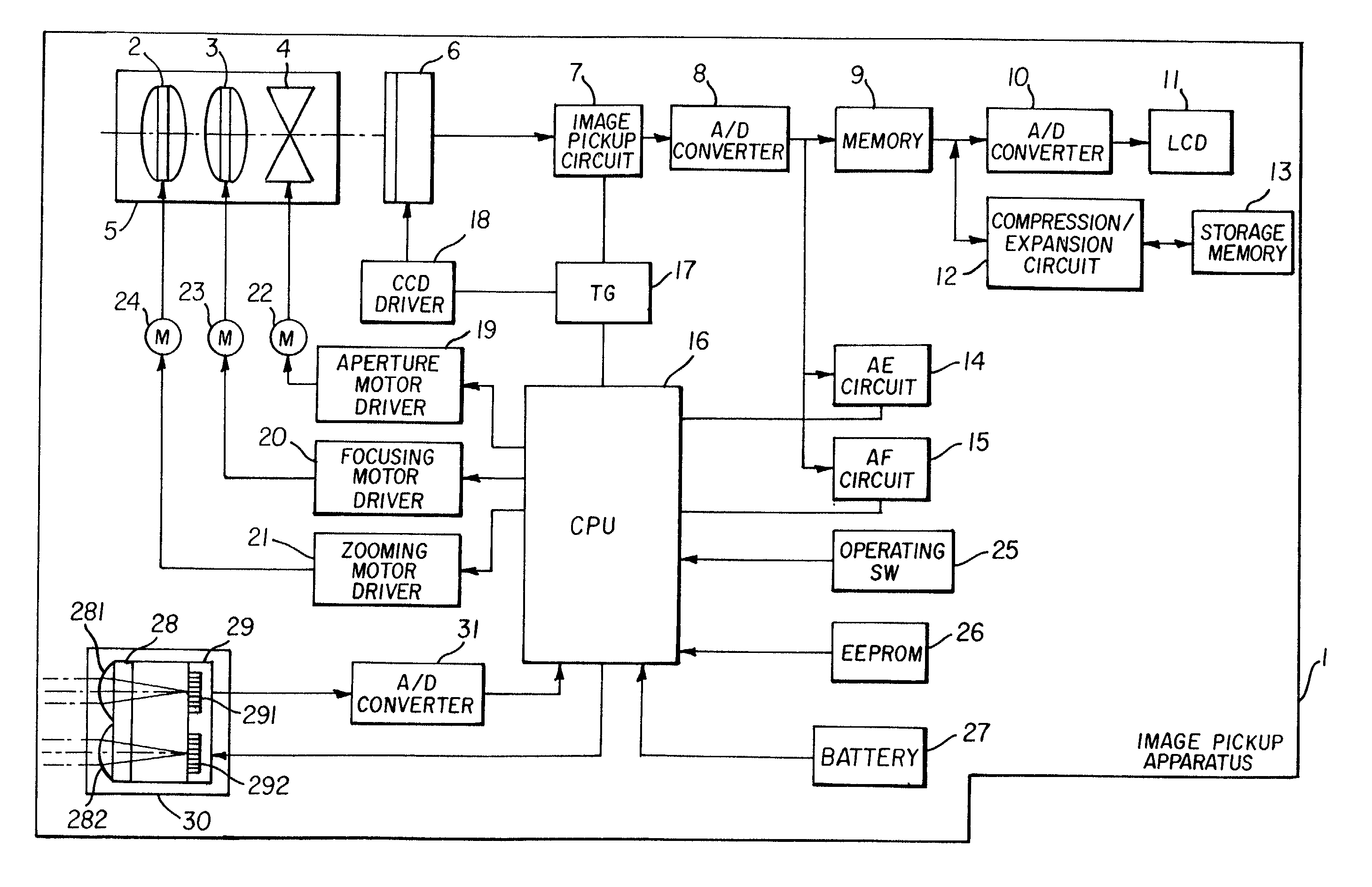
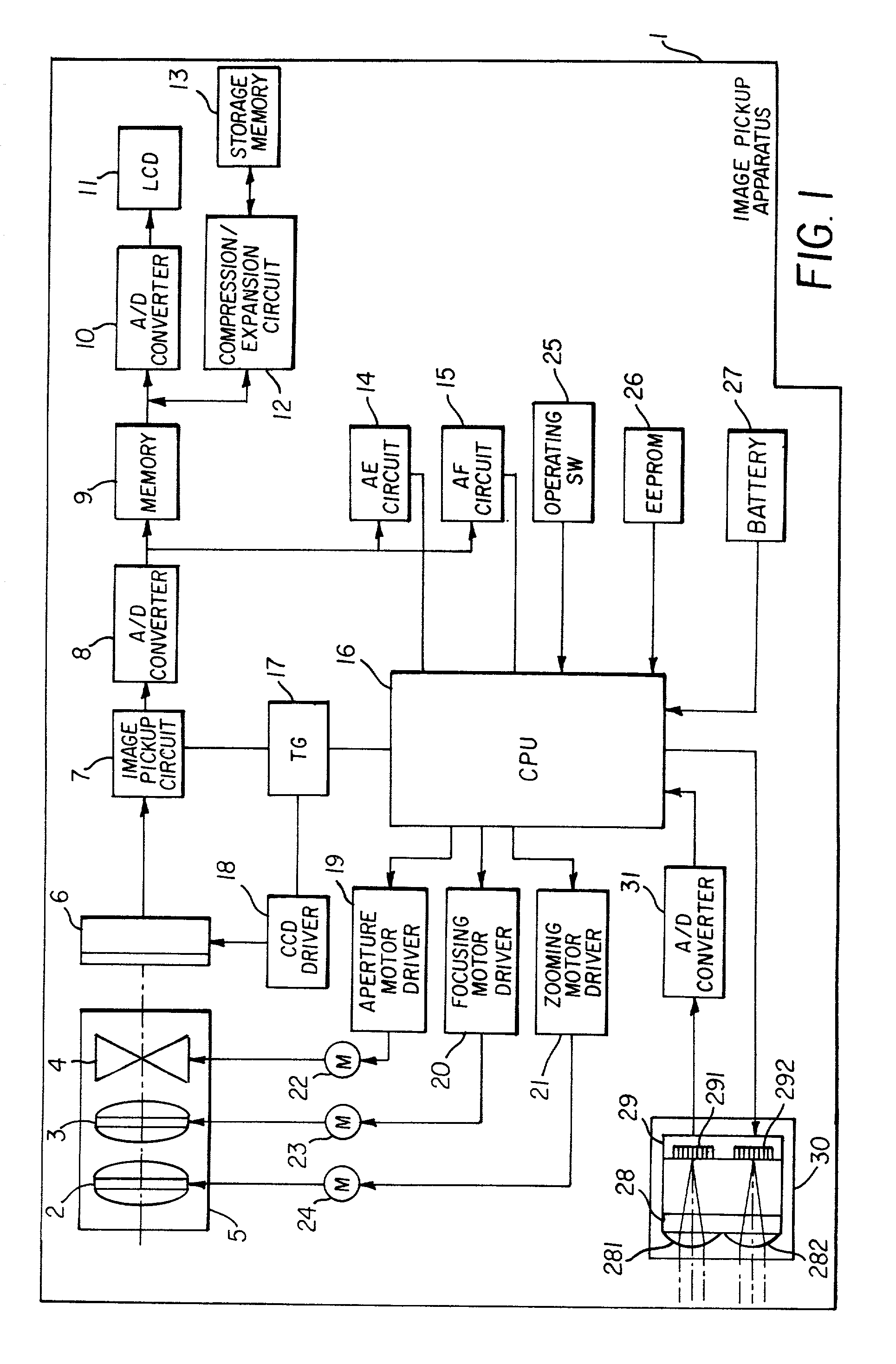
[0040]FIG. 1 is a block diagram of an electronic image pickup apparatus including an auto-focusing device according to the invention. Referring now to FIG. 1, the electronic image pickup apparatus 1 includes a lens mount 5 including a zoom lens 2 (including one or more lens elements), a focusing lens 3 (including one or more lens elements) and an aperture 4; a CCD (charge coupled device) 6; an image pickup circuit 7; an A / D (analog / digital) converter 8; a memory 9; a D / A (digital / analog) converter 10; an LCD (liquid crystal display) 11; a compression / expansion circuit 12; a storage memory 13; an AE (automatic exposure) circuit 14; an AF (auto-focusing) circuit 15; a CPU (central processing unit) 16, a TG (timing signal generator) 17, a CCD driver 18; an aperture motor driver 19; a focusing motor driver 20; a zooming motor driver 21; an aperture driving motor 22; a focusing motor 23; a zooming motor 24; operating SW's (switches) 25; an EEPROM (electrically-erasable programmable read-...


PUM


Abstract

An auto-focusing device and an electronic image pickup apparatus facilitates realizing a high focusing accuracy and a quick focusing operation simultaneously using an inexpensive plastic lens mount. The auto-focusing device according includes a means for correcting the conversion reference, if necessary, for converting the object distance measured by the open-control range finding means to a focusing position of the focusing lens based on the conversion reference and for moving the focusing lens to the converted focusing position. The electronic image pickup apparatus includes the auto-focusing device.

Description

FIELD OF THE INVENTION[0001]The present invention relates to an automatic focusing device (hereinafter referred to as an “auto-focusing device”) for focusing an image pickup lens automatically and electronic image pickup apparatuses such as an electronic still camera and a video camera, that mount the auto-focusing device thereon.BACKGROUND OF THE INVENTION[0002]The still camera and such electronic image pickup apparatuses employ image pickup devices such as charge coupled devices (CCD's) and metal oxide semiconductor (MOS) devices. The image pickup devices convert the optical image of an object picked up through an optical image pickup system to electric image signals. The electric image signals outputted from the image pickup devices are stored in a storage medium mounted on the electronic image pickup apparatus.[0003]Electronic image pickup apparatuses which include an auto-focusing device are in common use today. The auto-focusing device used for the electronic image pickup appa...

Claims


Application Information

Patent Timeline
Patent Type & Authority Patents(United States)
IPC IPC(8): G02B7/28G02B7/30G02B7/32G02B7/34G02B7/36G03B13/36H04N5/232
CPCG02B7/34G03B13/36H04N5/23212H04N5/23296H04N23/671H04N23/673H04N23/69
Inventor IZUMI, AKIO
Owner FUJI ELECTRIC CO LTD
Learn More