Eureka AIR delivers breakthrough ideas for toughest innovation challenges, trusted by R&D personnel around the world.

Wide band optical fiber amplifier

a wide-band, optical fiber technology, applied in the field of optical communication systems, can solve the problems of limited practical utility of raman amplifiers, insufficient bandwidth to amplify both c and l-bands, and amplifying techniques which have not been thoroughly proven, and achieve low noise, high amplification efficiency, and economic configuration

Inactive Publication Date: 2005-12-06
SAMSUNG ELECTRONICS CO LTD
View PDF16 Cites 4 Cited by
  • Summary
  • Abstract
  • Description
  • Claims
  • Application Information

AI Technical Summary

Benefits of technology

[0022]The present invention relates to a wide band erbium-doped fiber amplifier having an economical configuration and a high amplification efficiency while exhibiting a low noise figure.

Problems solved by technology

This bandwidth is insufficient to amplify both the C and L-band requiring approximately twice the bandwidth.
However, Raman amplifiers have limited practical utility because they require a high pumping power.
Also, tellulite-based erbium-doped fiber amplifiers are based on amplifying techniques which have not been thoroughly proven.
However, one drawback of most wide band erbium-doped fiber amplifiers is that they have a configuration in which independent C and L-bands are coupled in parallel.
One drawback of the conventional wide band optical fiber amplifier of the prior art, having the configuration above, is that the pumping light sources 150, 200, 230 require high power while exhibiting a low amplification efficiency.
A further drawback of the amplifier of FIG. 1 is that since the splitter 120, which exhibits an insertion loss of about 0.7 dB, is arranged upstream from the erbium-doped fibers a reduction in noise figure occurs.

Method used


Image

  • Wide band optical fiber amplifier
  • Wide band optical fiber amplifier
  • Wide band optical fiber amplifier

Examples


first embodiment

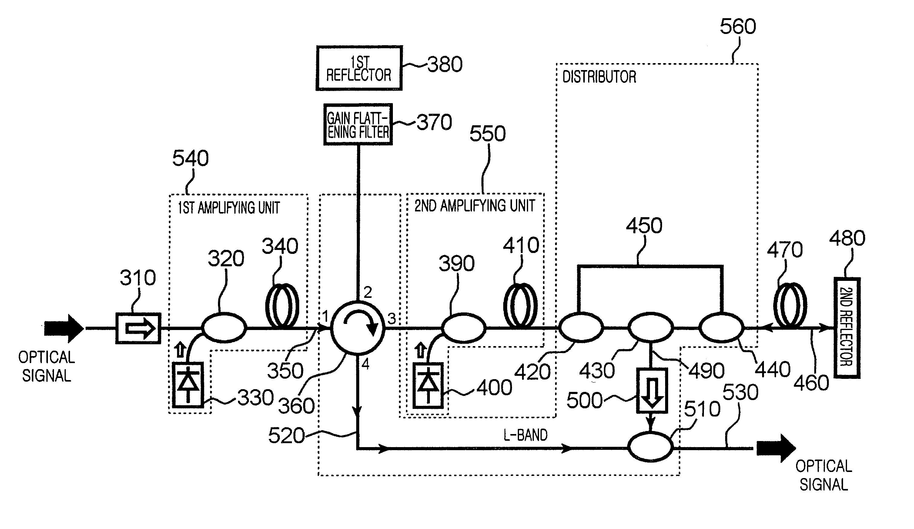
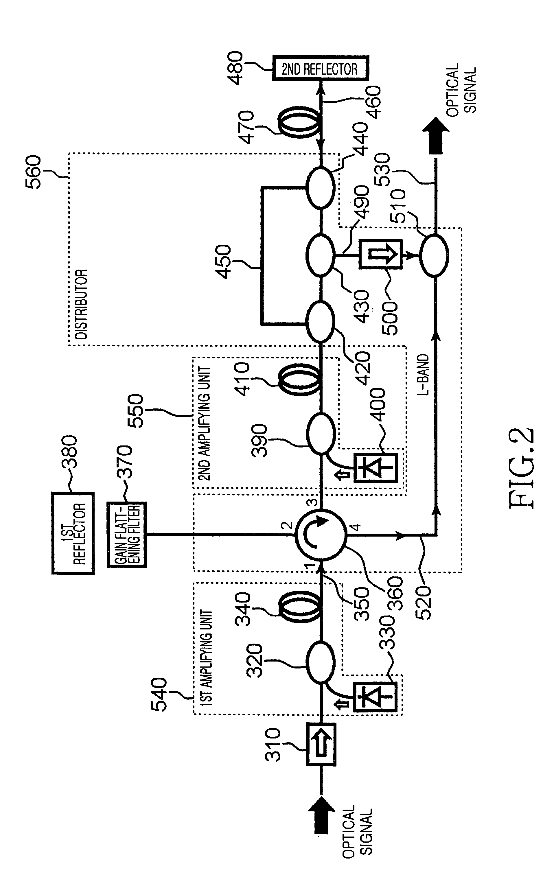
[0030]FIG. 2 illustrates the configuration of a wide band optical fiber amplifier according to the present invention. As shown in FIG. 2, the wide band optical fiber amplifier includes first and second isolators 310 and 500, first through third amplifying units 540, 550, and 470, a distributor 560, a gain flattening filter 370, and first and second reflecting units 380 and 480.

[0031]The first isolator 310 allows light inputted to the wide band optical fiber amplifier to pass in a forward direction, while preventing (blocking) light from flowing in a backward direction.

[0032]The first amplifying unit 540 includes a first wavelength selective coupler 320, a first pumping light source 330, and a first erbium-doped fiber 340.

[0033]The first wavelength selective coupler 320 couples C and L-band optical signal components received from the first isolator 310 with a pumping light outputted from the first pumping light source 330, and outputs a coupled C and L-band optical signal components ...

second embodiment

[0053

[0054]FIG. 3 illustrates the configuration of a wide band optical fiber amplifier according to a second embodiment of the present invention. As shown in FIG. 3, the wide band optical fiber amplifier includes first and second isolators 610 and 750, first through third amplifying units 785, 660, and 795, a gain flattening filter 650, a distributor 790, and a reflecting unit 740.

[0055]The first isolator 610 allows light inputted to the wide band optical fiber amplifier to pass forward through the wide band optical fiber amplifier, while blocking light flowing in the opposite direction.

[0056]The first amplifying unit 785 includes a first wavelength selective coupler 620, a first pumping light source 630, and a first erbium-doped fiber 640.

[0057]The first wavelength selective coupler 620 couples C and L-band optical signal components received from the first isolator 610 with a pumping light received from the first pumping light source 630, and outputs the coupled C and L-band optica...

third embodiment

[0076

[0077]FIG. 4 illustrates the configuration of a wide band optical fiber amplifier according to a third embodiment of the present invention. As shown in FIG. 4, the wide band optical fiber amplifier includes first and second isolators 810 and 930, first and second amplifying units 985 and 995, a gain flattening filter 940, a distributor 990, and a reflecting unit 920. C and L-band

[0078]In operation, when the C and L-band optical signal components are inputted to the wide band optical fiber amplifier, the C and L-band signals first pass through the first isolator 810, and then the first wavelength selective coupler 820, after which the C and L-band signals enter the first erbium-doped fiber 840. After being amplified in the first erbium-doped fiber 840, the C and L-band optical signal components are applied to the splitter 860. The optical signal applied to the splitter 860 are split into C and L-band optical signal components respectively, whereby the C-band optical signal is ou...


PUM


Abstract

Disclosed is a wide band optical fiber amplifier for amplifying C and L-band optical signal components having an economical configuration, high amplification efficiency while exhibiting a low noise figure. The amplifier includes first and second isolators; first, second, and third amplification units; a distributor; a gain flattening filter; and first and second reflectors. The amplifier receives C and L band optical signals and process the signals by: amplifying C and L band signals; gain flattening the only C band signal twice; amplifying C and L band signals for the second time; splitting the C band signal from L band signal; subjecting L band signal to be amplified three more times; and combining resulting C and L band signals.

Description

CLAIM OF PRIORITY[0001]This application makes reference to, incorporates the same herein, and claims all benefits accruing under 35 U.S.C. § 119 arising from an application entitled, WIDE BAND OPTICAL FIBER AMPLIFIER, earlier filed in the Korean Industrial Property Office on Mar. 11, 2002, and there duly assigned Serial No. 2002-12835.BACKGROUND OF THE INVENTION[0002]1. Field of the Invention[0003]The present invention relates to optical communication systems, and more particularly to an optical fiber amplifier disposed between an optical transmission block and an optical receiver block in an optical communication system.[0004]2. Description of the Related Art[0005]To keep abreast of exponentially growing data demand, wavelength division multiplexing (WDM) optical transmission systems will be required to have expanded transmission bandwidth range. In this regard, a number of active research efforts are ongoing in conjunction with wide band systems that use both the C-band (Conventio...

Claims


Application Information

Patent Timeline
Patent Type & Authority Patents(United States)
IPC IPC(8): G02B6/00H01S3/10
CPCH04B10/2941G02B6/00
Inventor HWANG, SEONG-TAEKSONG, KWAN-WOONG
Owner SAMSUNG ELECTRONICS CO LTD
Why Eureka
Eureka Blog
Learn More