
Exploiting shortest path for improved network clock distribution

a network clock and shortest path technology, applied in the field of signal distribution, can solve the problems of unsatisfactory in large network environments, delay in actual signals, etc., and achieve the effects of enhancing signal contribution, reducing delay, and improving signal to noise ration

Active Publication Date: 2005-12-06
CIRRUS LOGIC INC
View PDF14 Cites 2 Cited by
  • Summary
  • Abstract
  • Description
  • Claims
  • Application Information

AI Technical Summary

Benefits of technology

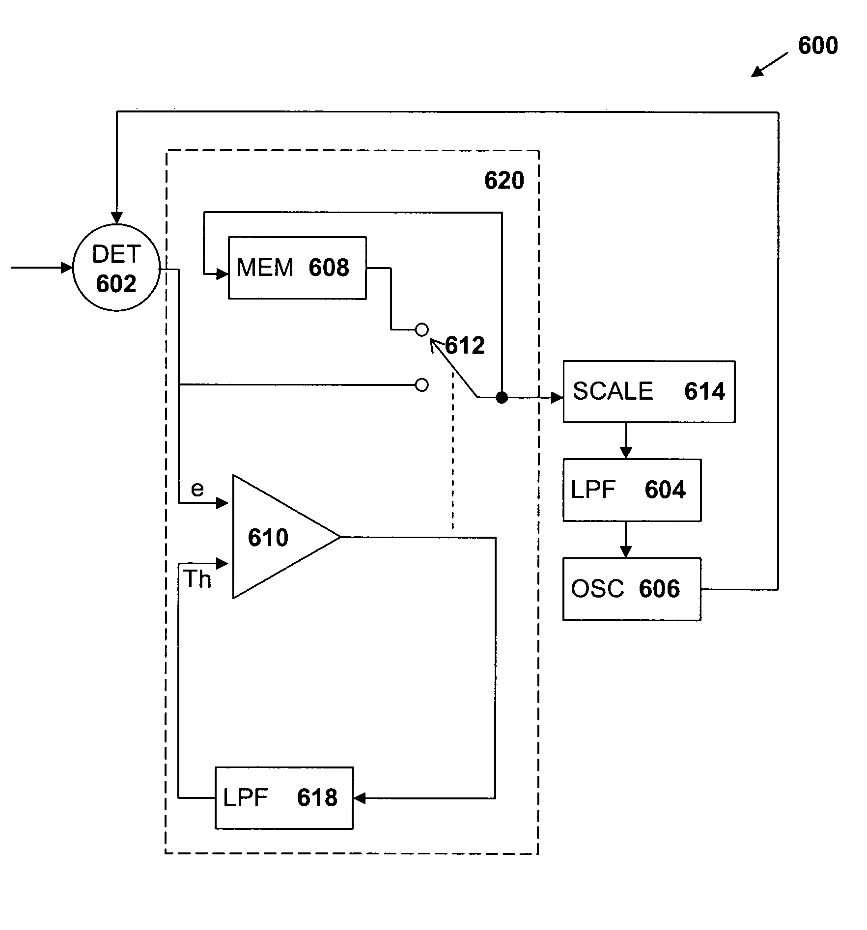
[0006]The present invention provides apparatus and methods for exploiting the existence of a shortest path between a source device and a destination device by identifying the shortest path and using the signal which has taken the shortest path in preference to delayed transmissions or delayed images of the same signal, thereby improving signal to noise ration seen by a PLL. The present invention provides a processor between a phase-sensitive detector and a low pass filter of a phase locked loop. In one embodiment, the processor includes a scaler, such as an exponential scaler, providing asymmetrical error weighting to enhance the contribution of signals with a smaller delay (shorter path).
[0007]In a second embodiment, the processor further includes a self-adjusting threshold to prevent the PLL from free running in the “masked” state for an extended period of time. When the PLL is operating normally, the threshold level is gradually increased, thus decreasing the width of the mask, until many errors are ignored and only a fixed percentage of the lowest delay signals from the detector are passed to the low pass filter to enable the PLL to regain lock.

Problems solved by technology

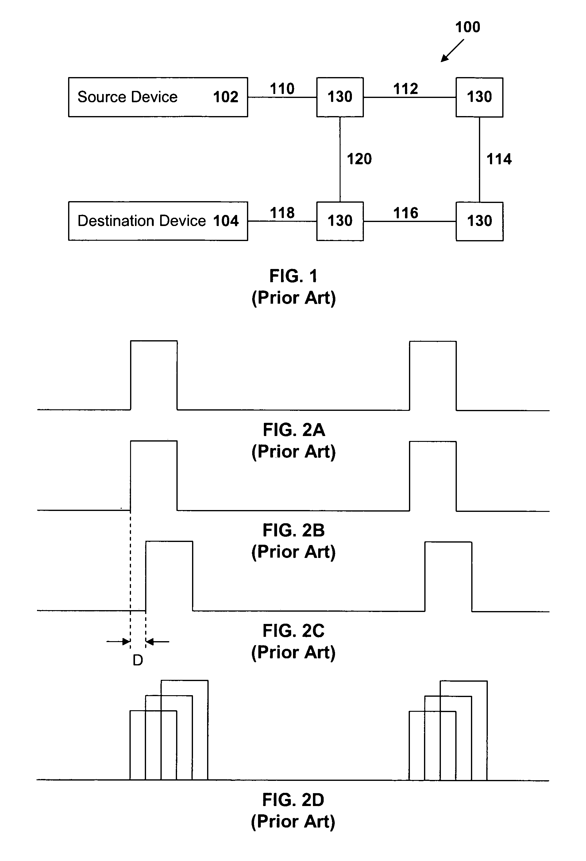
However, because of multiple-path delays or congestion, the signal taken by one path will arrive at the target device at a slightly different time relative to the signal taken by another path or experiencing a different congestion scenario (that is, delays due to other signals having a higher priority).
However, due to the factors noted above, and others, a delay will occur in the actual signal, as is apparent in FIG. 2C.
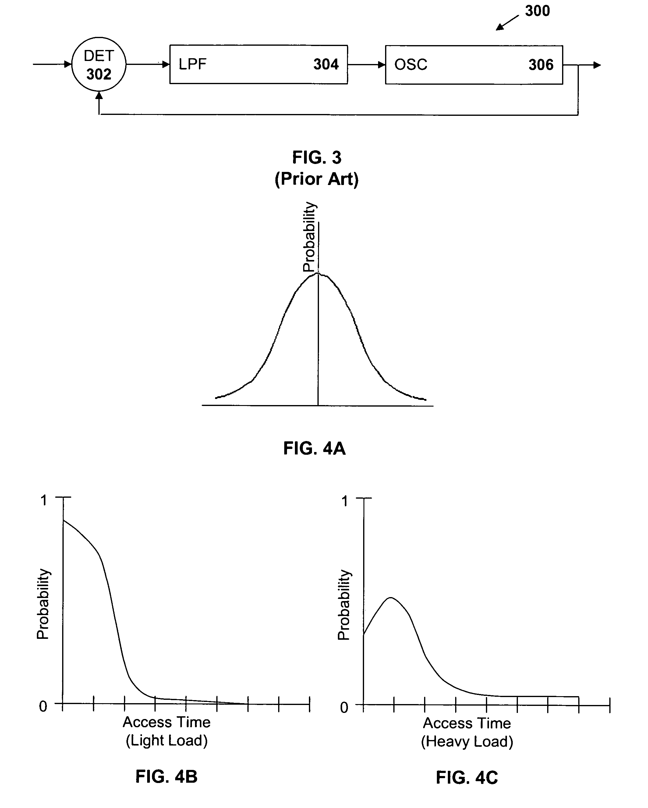
And, although such a probability curve may be satisfactory for small, local networks in which the network architecture is controllable, it is not satisfactory in larger network environments, including wide area and wireless networks which have a wider range of delay variation as shown in FIG. 4C.

Method used


Image

  • Exploiting shortest path for improved network clock distribution
  • Exploiting shortest path for improved network clock distribution
  • Exploiting shortest path for improved network clock distribution

Examples


Embodiment Construction

[0020]FIG. 5 is a block diagram of one embodiment of circuitry 500 of the present invention. The detector 500 includes a dual-input phase-sensitive detector 502, a low pass filter 504, and a voltage-controlled oscillator 506, elements common to the PLL of FIG. 3. Additionally, the device 500 includes a processor 520, such as an exponential scaler 508, coupled between the detector 502 and the low pass filter 504. The scaler 508 exaggerates the effects of small errors (which represent small delays and are close to the ideal in FIG. 4B) and reduces the effects of larger errors (which represent larger errors and are farther from the ideal). Thus, while the device generates an average, the average generated is closer to the ideal.

[0021]FIG. 6 is a block diagram of a second embodiment of the device 600 of the present invention. The device 600, includes a dual-input phase-sensitive detector 602, a low pass filter 604, and a voltage-controlled oscillator 606 and a processor 620 comprising a...


PUM


Abstract

Apparatus and methods are provided for exploiting the existence of a shortest path between a source device and a destination device by identifying the shortest path and using the signal which has taken the shortest path in preference to delayed transmissions or delayed images of the same signal, thereby improving signal distribution. The present invention provides a processor between a phase-sensitive detector and a low pass filter of a phase locked loop for selecting and driving the PLL primarily from the signal which has taken the shortest path.

Description

TECHNICAL FIELD[0001]The present invention relates generally to the field of signal distribution and, in particular, to improved signal reception in a network or other computing environment in which a signal may take several paths to its destination, each path having an associated delay.BACKGROUND ART[0002]In many computing or communications environments, a resource is shared among several or many devices. Numerous devices may be interconnected and various signals are transmitted among the devices. A signal from a source device may be directed to a selected target device. However, because of multiple-path delays or congestion, the signal taken by one path will arrive at the target device at a slightly different time relative to the signal taken by another path or experiencing a different congestion scenario (that is, delays due to other signals having a higher priority). In either situation, a delay variation will exist among the signals. As illustrated schematically in FIG. 1, a mu...

Claims


Application Information

Patent Timeline
IPC IPC(8): H04L29/08
CPCH04L69/323
Inventor GROSS, KEVIN PAUL
Owner CIRRUS LOGIC INC
Learn More