
System and method for communicating optical signals between a data service provider and subscribers

a data service provider and optical signal technology, applied in multiplex communication, wavelength-division multiplex systems, two-way working systems, etc., can solve the problems of too many optical cables that must originate at the head end or data service hub, prohibitive ftth and fttb architecture, and inapplicability of the system, so as to reduce the number of connections, and improve the effect of symmetrical data transmission

Inactive Publication Date: 2005-12-06
ARRIS SOLUTIONS
View PDF68 Cites 34 Cited by
  • Summary
  • Abstract
  • Description
  • Claims
  • Application Information

AI Technical Summary

Benefits of technology

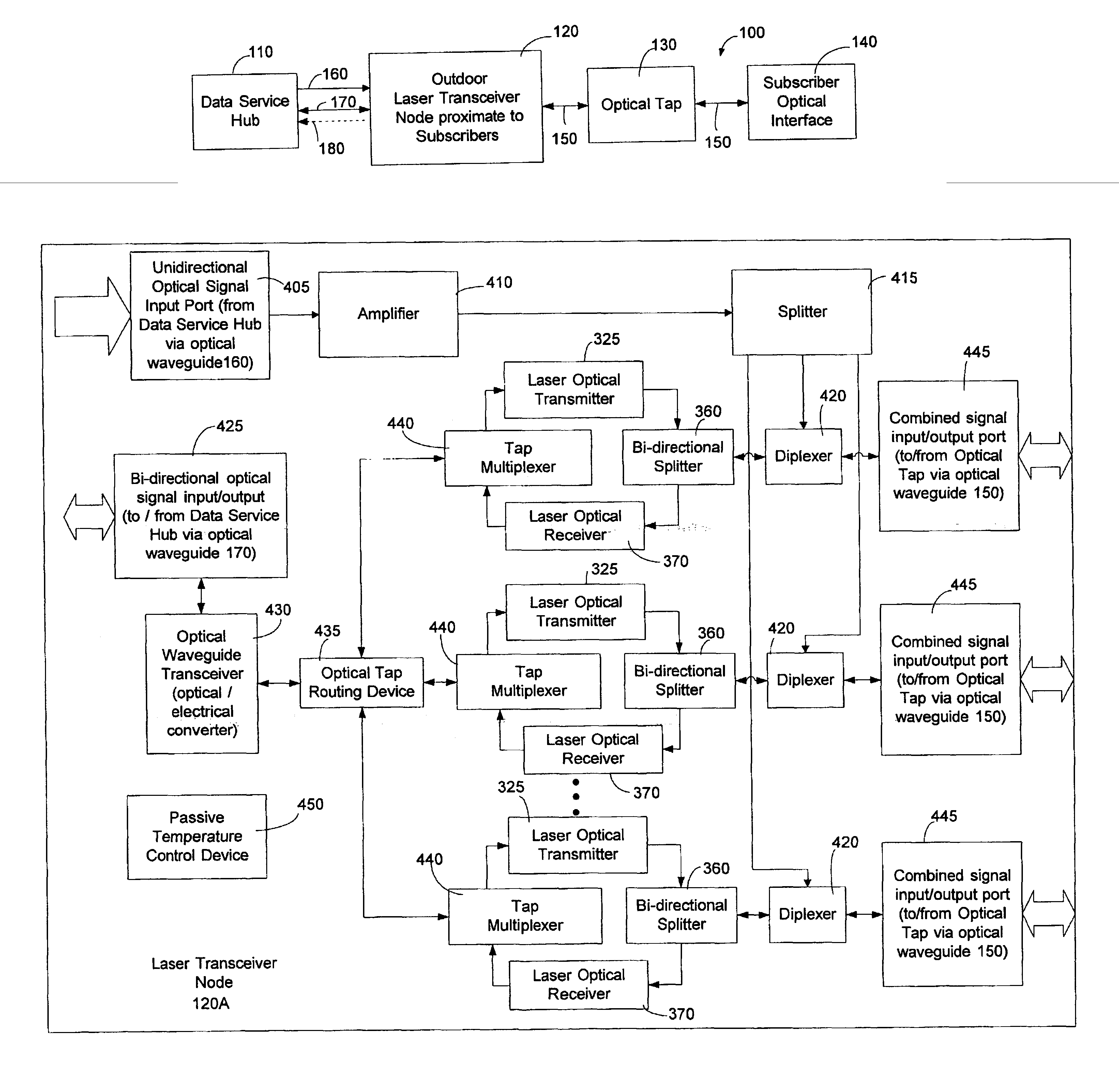
[0026]The laser transceiver node can also provide high speed symmetrical data transmission. In other words, the laser transceiver node can propagate the same bit rates downstream and upstream from a network subscriber. Further, the laser transceiver node can also serve a larger number of subscribers while reducing the number of connections at the data service hub.
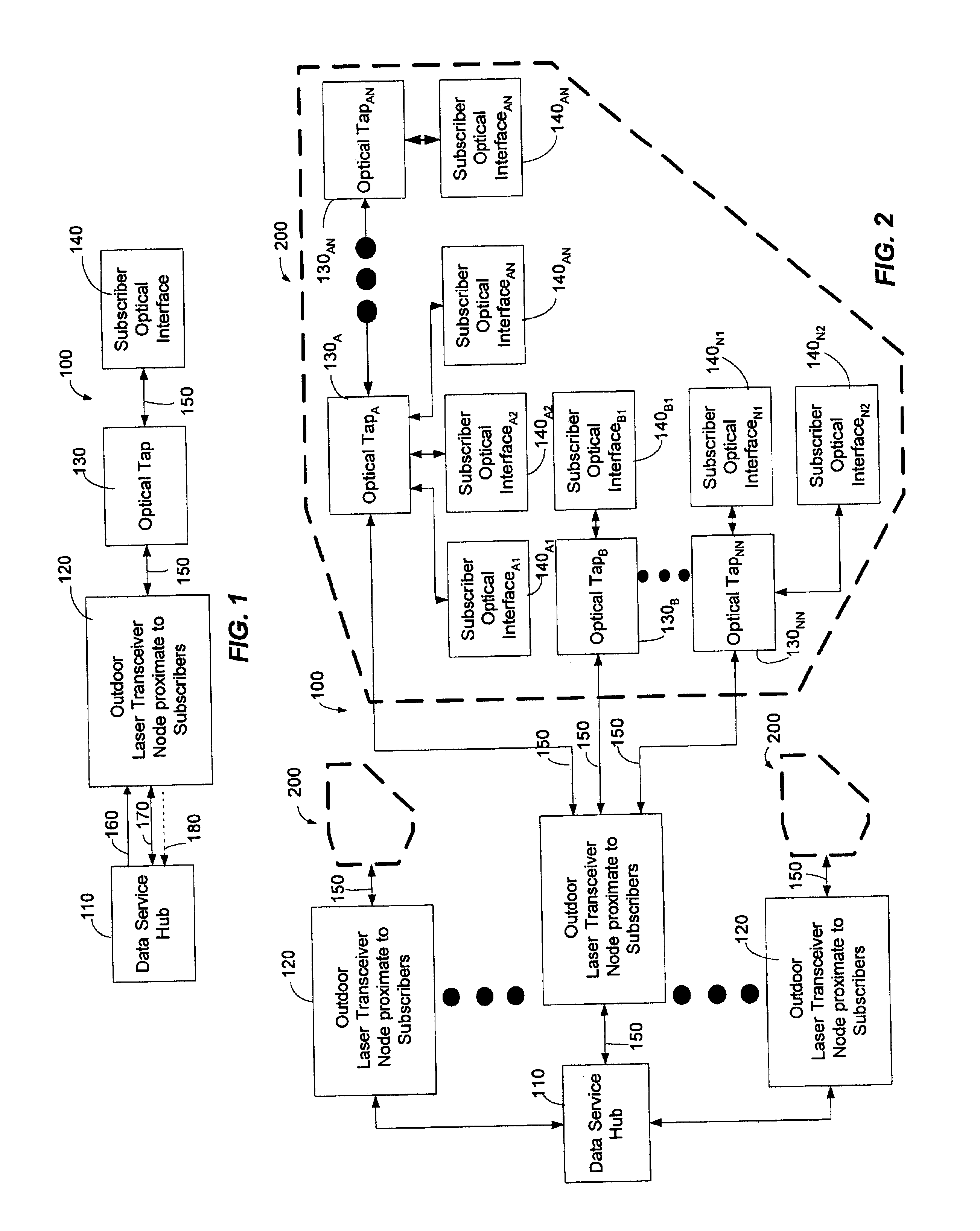
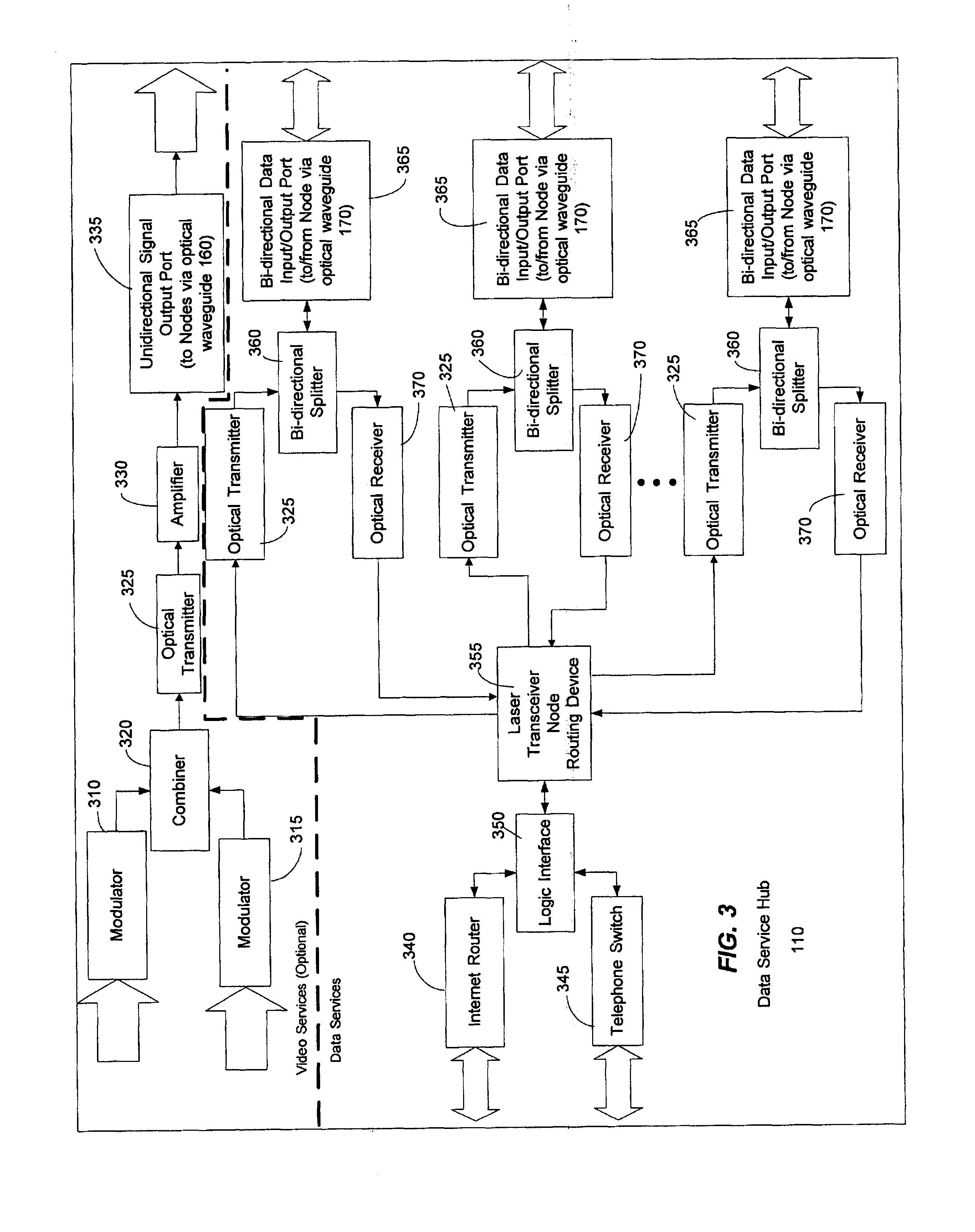
[0027]The flexibility and diversity of the laser transceiver node can be attributed to at least a few components. The laser transceiver node can comprise an optical tap routing device that is coupled to one or more tap multiplexers. The optical tap routing device can manage the interface with the data service hub optical signals and can route or divide or apportion the data service hub signals according to individual tap multiplexers that modulate laser transmitters to generate optical signals for specific optical taps. That is, unlike conventional routers which assign single ports to respective individual subscribers, the optical tap routing device can assign multiple subscribers to a single port. More specifically, each tap multiplexer connected to a port of the optical tap routing device can service groups of subscribers. The individual tap multiplexers can modulate laser transmitters to supply downstream optical signals to preassigned groups of subscribers coupled to optical taps. From the optical taps, subscribers can receive the downstream optical signals with subscriber optical interfaces.
[0030]The laser transceiver node is but one part of the present invention. The present invention also comprises an efficient coupler, referred to as an optical tap, between the laser transceiver node and a respective subscriber optical interface. The optical tap can divide optical signals between a plurality of subscribers and can be simple in its design. For example, each optical tap can comprise an optical splitter that may feed one or more subscribers. Optical taps can be cascaded or they can be connected in a star architecture from the laser transceiver node. The optical tap can also route signals to other optical taps that are downstream relative to a respective optical tap. The optical tap can also connect to a small number of optical waveguides so that high concentrations of optical waveguides are not present at any particular laser transceiver node. In other words, the optical tap can connect to a predetermined number of optical waveguides at a point remote from the laser transceiver node so that high concentrations of optical waveguides at the laser transceiver node can be avoided.

Problems solved by technology

However, in the past, the cost of FTTH and FTTB architectures have been considered prohibitive.
While the PON architecture does provide an all fiber network, it has many drawbacks that make such a system impractical to implement.
One drawback of the PON architecture is that too many optical cables must originate at the head end or data service hub due to limitations in the number of times an optical signal can be divided before the signal becomes too weak to use.
Another drawback can be attributed to the passive nature of a PON network.
Another significant drawback of the PON architecture is the high cost of the equipment needed at the data service hub.
To support this protocol, rather complex and expensive equipment is needed.
In addition to the high data service hub costs, conventional PON architectures do not lend themselves to efficient upgrades.
The data speeds in the downstream and upstream directions is another drawback of the PON architecture.
Such unbalanced communication speeds between the upstream and downstream communication directions is undesirable and is often referred to as asymmetrical bandwidth.
The assymetrical bandwidth is a result of the high cost of optical components required.
The connectivity between data ports and optical fibers with this conventional FTTH / HFC architecture yields a very fiber intensive last mile.
The use of coaxial cables in the FTTH / HFC architecture adds to the overall cost of the system because two separate and distinct networks are present in such an architecture.
In other words, the FTTH / HFC architecture has high maintenance costs because of the completely different waveguides (coaxial cable in combination with optical fiber) in addition to the electrical and optical equipment needed to support such two distinct systems.
Another drawback of the FTTH / HFC architecture is that the active signal source between the data service hub and subscriber, usually referred to as the router, requires a protected environment that occupies a significant amount of space.
Another drawback of the conventional HFC architecture exists at the data service hub where numerous communication devices are needed to support the data signals propagating along the optical fibers between the active signal source and the data service hub.
Another drawback of the conventional HFC architecture flows from the use of the CMTS.
Similar to the passive optical network (PON) discussed above, the CMTS cannot support symmetrical bandwidth.
The nature of the DOCSIS standard is that it limits the upstream bandwidth available to subscribers.
This can be a direct result of the limited upstream bandwidth available in an HFC plant.
Such a property is undesirable for subscribers who need to transmit more complex data for bandwidth intensive services such as home servers or the exchange of audio files over the Internet.

Method used


Image

  • System and method for communicating optical signals between a data service provider and subscribers
  • System and method for communicating optical signals between a data service provider and subscribers
  • System and method for communicating optical signals between a data service provider and subscribers

Examples


Embodiment Construction

[0049]The present invention may be embodied in hardware or software or a combination thereof disposed within an optical network. The present invention can comprise a laser transceiver node disposed between a data service hub and a subscriber that can allocate additional or reduced bandwidth based upon the demand of one or more subscribers. The present invention can support one gigabit or faster Ethernet communications in optical form to and from the data service hub and partition or apportion this optical bandwidth into distribution groups of a predetermined number. The present invention allows bandwidth to be offered to subscribers in preassigned increments. The flexibility and diversity of the present invention can be attributed to a few components.

[0050]The laser transceiver node of the present invention can comprise an optical tap routing device that is coupled to one or more tap multiplexers. The optical tap routing device can assign multiple subscribers to a single port that r...


PUM


Abstract

An optical fiber network can include an outdoor laser transceiver node that can be positioned in close proximity to the subscribers of an optical fiber network. The outdoor laser transceiver node does not require active cooling and heating devices that control the temperature surrounding the laser transceiver node. The laser transceiver node can adjust a subscriber's bandwidth on a subscription basis or on an as-needed basis. The laser transceiver node can also offer data bandwidth to the subscriber in preassigned increments. Additionally, the laser transceiver node lends itself to efficient upgrading that can be performed entirely on the network side. The laser transceiver node can also provide high speed symmetrical data transmission. Further, the laser transceiver node can utilize off-the-shelf hardware to generate optical signals such as Fabry-Perot (F-P) laser transmitters, distributed feed back lasers (DFB), or vertical cavity surface emitting lasers (VCSELs).

Description

PRIORITY CLAIM TO PROVISIONAL APPLICATIONS[0001]The present application claims priority to provisional patent application entitled, “Systems to Provide Video, Voice and Data Services via Fiber Optic Cable,” filed an Oct. 4, 2000 and assigned U.S. application Ser. No. 60 / 237,894; provisional patent application entitled, “Systems to Provide Video, Voice and Data services via Fiber Optic Cable—Part 2,” filed on Oct. 26, 2000 and assigned U.S. application Ser. No. 60 / 244,052; provisional patent application entitled, “Systems to Provide Video, Voice and Data services via Fiber Optic Cable—Part 3,” filed on Dec. 28, 2000 and assigned U.S. application Ser. No. 60 / 258,837; provisional patent application entitled, “Protocol to Provide Voice and Data Services via Fiber Optic Cable,” filed on Oct. 27, 2000 and assigned U.S. application Ser. No. 60 / 243,978; and provisional patent application entitled, “Protocol to Provide Voice and Data Services via Fiber Optic Cable—Part 2,” filed on May 8, 20...

Claims


Application Information

Patent Timeline
Patent Type & Authority Patents(United States)
IPC IPC(8): H04B10/272H04J14/02H04N7/173H04N7/22H04Q11/00
CPCH04J14/028H04J14/0282H04J14/0286H04N7/22H04Q11/0067H04J14/0232H04J14/0238H04J14/0247H04J14/0252H04J14/0226H04Q11/0071
Inventor FARMER, JAMES O.KENNY, JOHN J.QUINN, PATRICK W.TIGHE, THOMAS A.WHITTLESEY, PAUL F.VELLA, EMMANUEL A.
Owner ARRIS SOLUTIONS
Learn More