System and method for communicating optical signals between a data service provider and subscribers

US20050074241A1Inactive Publication Date: 2005-04-07ARRIS SOLUTIONS

Image

  • System and method for communicating optical signals between a data service provider and subscribers
  • System and method for communicating optical signals between a data service provider and subscribers
  • System and method for communicating optical signals between a data service provider and subscribers

Examples


Embodiment Construction

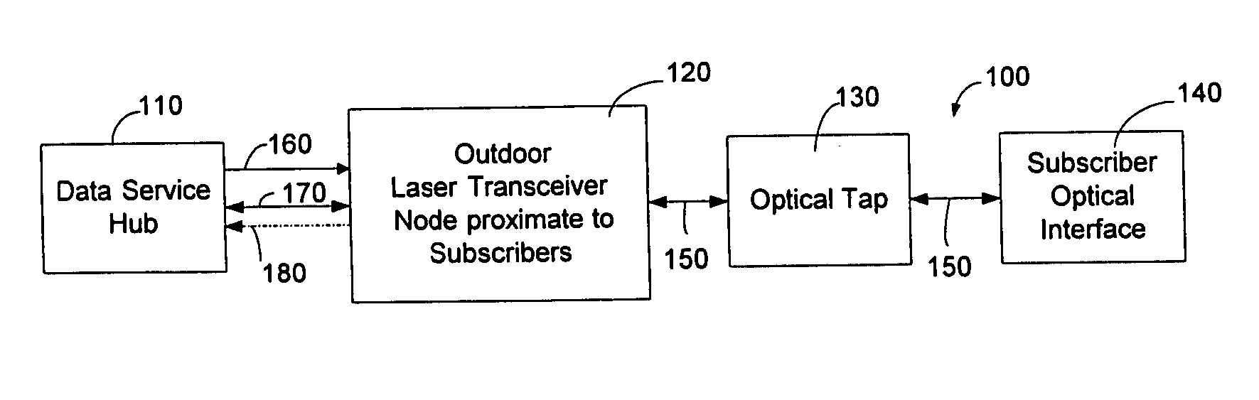
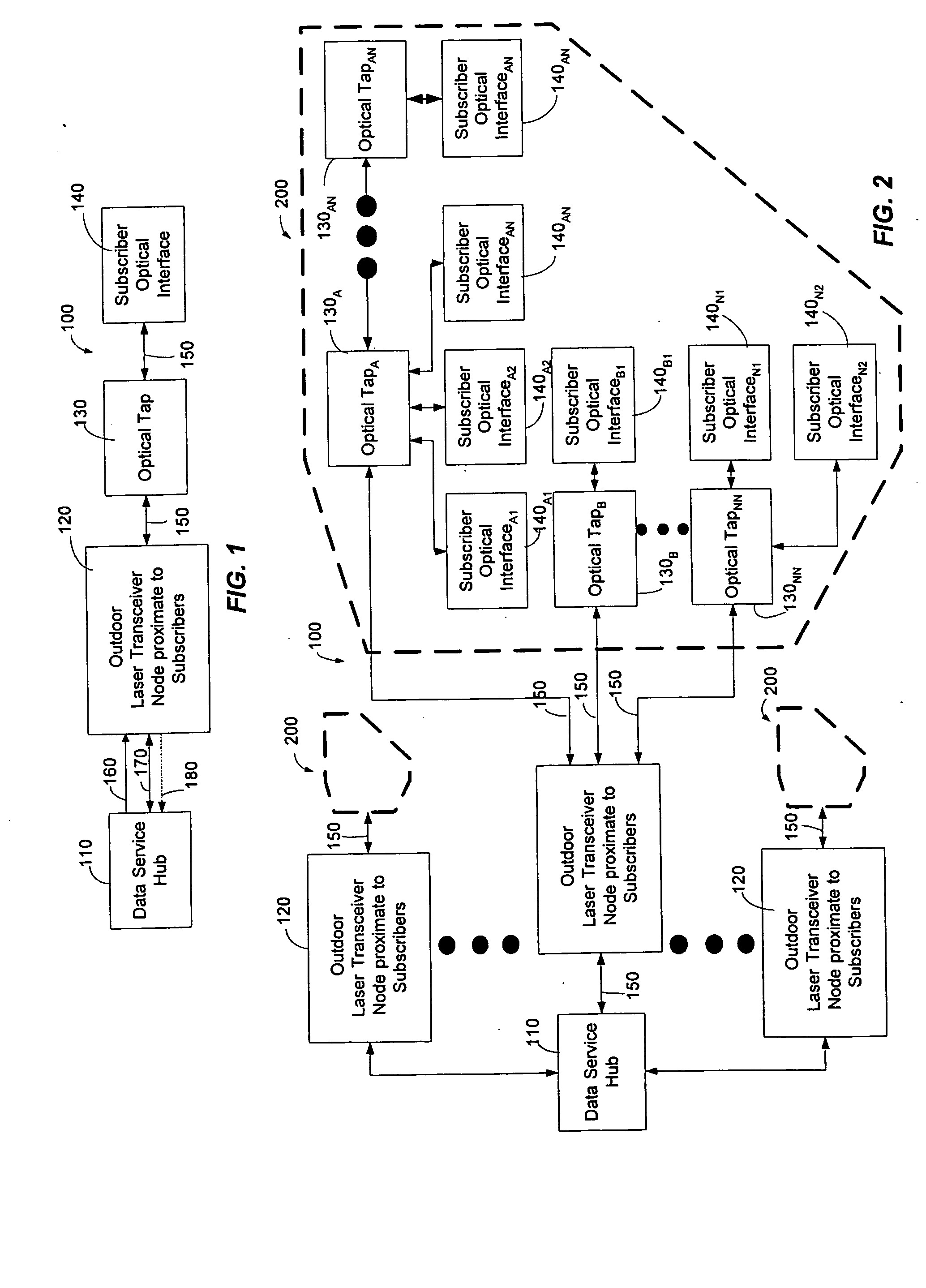
[0049] The present invention may be embodied in hardware or software or a combination thereof disposed within an optical network. The present invention can comprise a laser transceiver node disposed between a data service hub and a subscriber that can allocate additional or reduced bandwidth based upon the demand of one or more subscribers. The present invention can support one gigabit or faster Ethernet communications in optical form to and from the data service hub and partition or apportion this optical bandwidth into distribution groups of a predetermined number. The present invention allows bandwidth to be offered to subscribers in preassigned increments. The flexibility and diversity of the present invention can be attributed to a few components.

[0050] The laser transceiver node of the present invention can comprise an optical tap routing device that is coupled to one or more tap multiplexers. The optical tap routing device can assign multiple subscribers to a single port tha...


PUM


Abstract

An optical fiber network can include an outdoor laser transceiver node that can be positioned in close proximity to the subscribers of an optical fiber network. The outdoor laser transceiver node does not require active cooling and heating devices that control the temperature surrounding the laser transceiver node. The laser transceiver node can adjust a subscriber's bandwidth on a subscription basis or on an as-needed basis. The laser transceiver node can also offer data bandwidth to the subscriber in preassigned increments. Additionally, the laser transceiver node lends itself to efficient upgrading that can be performed entirely on the network side. The laser transceiver node can also provide high speed symmetrical data transmission. Further, the laser transceiver node can utilize off-the-shelf hardware to generate optical signals such as Fabry-Perot (F-P) laser transmitters, distributed feed back lasers (DFB), or vertical cavity surface emitting lasers (VCSELs).

Description

PRIORITY CLAIM TO PROVISIONAL APPLICATIONS [0001] The present application claims priority to provisional patent application entitled, “Systems to Provide Video, Voice and Data Services via Fiber Optic Cable,” filed on Oct. 4, 2000 and assigned U.S. Application Ser. No. 60 / 237,894; provisional patent application entitled, “Systems to Provide Video, Voice and Data services via Fiber Optic Cable—Part 2,” filed on Oct. 26, 2000 and assigned U.S. Application Ser. No. 60 / 244,052; provisional patent application entitled, “Systems to Provide Video, Voice and Data services via Fiber Optic Cable—Part 3,” filed on Dec. 28, 2000 and assigned U.S. Application Ser. No. 60 / 258,837; provisional patent application entitled, “Protocol to Provide Voice and Data Services via Fiber Optic Cable,” filed on Oct. 27, 2000 and assigned U.S. Application Ser. No. 60 / 243,978; and provisional patent application entitled, “Protocol to Provide Voice and Data Services via Fiber Optic Cable—Part 2,” filed on May 7, ...

Claims


Application Information

Patent Timeline
07 Apr 2005
Publication
US20050074241A1
IPC
H04B10/272; H04J14/02; H04N7/173; H04N7/22; H04Q11/00
CPC
H04J14/0226; H04J14/028; H04J14/0282; H04J14/0286; H04J14/0298; H04N7/17309; H04J14/0238; H04Q11/0067
Inventors
FARMER, JAMES O.; KENNY, JOHN J.