Control module for flywheel operated hand tool

a control module and hand tool technology, applied in the direction of manufacturing tools, percussive tools, portable drilling machines, etc., can solve the problems of inability or not desire, on-site air compressor, and often impediment of user dragging pneumatic umbilicals, so as to avoid human errors

Inactive Publication Date: 2005-12-13
SENCO BRANDS
View PDF19 Cites 60 Cited by
  • Summary
  • Abstract
  • Description
  • Claims
  • Application Information

AI Technical Summary

Benefits of technology

[0015]These and other problems in the prior art are addressed by a control module that is responsive to a rotary speed of a rotational member of an electrically powered hand tool and is responsive to an adjustable target speed for the rotational member. Thereby, the control module more consistently controls the hand tool, avoiding human error and the inconvenience of relying upon the user to modulate the speed of the tool.
[0016]In one aspect of the invention, a control module for a hand tool includes a speed setting that is used for presetting the control module to an operating range of the intended rotational member of the hand tool. Thus, the control module is readily adjusted to the operating environment, using the speed setting as a target for comparing a sensed speed.
[0017]In another aspect of the invention, a method of controlling a fastener-driving tool enforces a user input sequence to ensure that a fastener is driven into a workpiece. In particular, a safety signal is received from a safety switch indicating a nose assembly of the tool is against a workpiece. A safety time-out value is accessed. The duration of depression of the safety signal is timed. Then, the tool is activated to drive a fastener in response to receiving a trigger signal from a trigger switch before the timed duration of the safety signal exceeds the safety time-out value. By so enforcing this sequence, a user is less likely to inadvertently drive a fastener in instances where the trigger is inadvertently squeezed and the tool contacts a surface.

Problems solved by technology

However, pneumatic driving tools require an on-site air compressor, which is often unavailable or not desired.
Also, dragging the pneumatic umbilical is often an impediment to the user.
In particular, much effort has been expended in the prior art in providing heavy duty, high powered, fastener driving tools employing a flywheel as a means of delivering kinetic energy sufficient to drive a heavy duty fasteners.
While such corded electrical fastener driving tools may perform well, in many instances an AC outlet is not available.
Even if an AC outlet is available, many users find dragging the electrical cord to be an impediment to use.
The relatively small amount of energy stored in the spring each cycle typically requires a large number of impacts to drive a staple or nail into a workpiece.
The multiple impact tools also can damage a wood surface due to the vibrations the tool generates while stroking.
However, using a battery has been thwarted by a number of challenges.
First, each specific application generally requires a fastener drive assembly and motor customized for the type of fastener.
Thus, each specific application was thought to require a custom control module, with the increased costs of design, manufacture and support.
Even assuming that various types of fasteners could then be used with a family of flywheel operated hand tools, each tool would suffer the disadvantages inherent in using battery power.
The rotary speed of the flywheel varies with the battery voltage, and thus the depth of drive of the fastener would unacceptably vary.
The generally known controllers for corded flywheel operated hand tools are unable to accommodate these power variations.
Furthermore, even for a specific application, the desired depth of drive is affected by the type of work piece into which the fastener is driven and to user preferences.
Although the increased functionality of the control module in such pneumatic tools has advantages, these control modules are not responsive to changes in operating conditions to vary the depth of drive.

Method used


Image

  • Control module for flywheel operated hand tool
  • Control module for flywheel operated hand tool
  • Control module for flywheel operated hand tool

Examples


Embodiment Construction

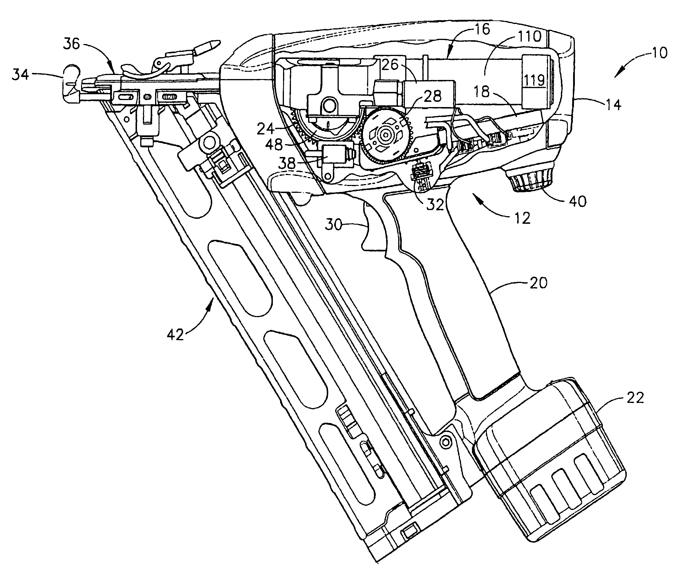
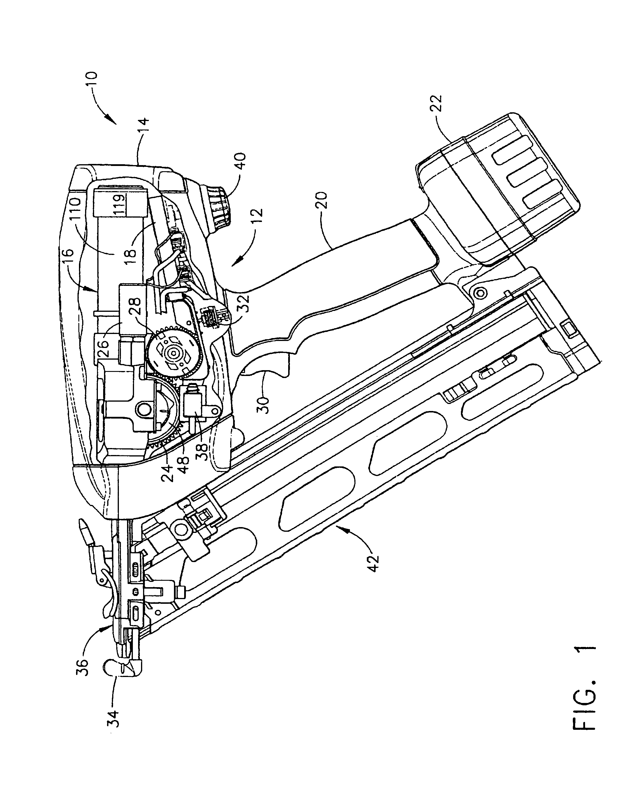
[0048]With reference to FIG. 1, wherein like numbers refer to like components throughout the several views, a portable flywheel operated hand tool, depicted as a hand-held nailing tool 10, includes a control system 12 that advantageously provides consistent speed control throughout a range of operating conditions. In particular, the nailing tool 10 generally comprises a housing or main body 14 enclosing a fastener drive assembly 16 and a control module 18, and further includes and a gripping handle 20. Attached to the end of handle 20 is a removable, rechargeable battery 22 for providing the necessary electrical energy to operate a DC motor 24 and a solenoid 26 of the fastener drive assembly 16, as well as the electrical control module 18. Unlike generally known batteries that are required to handle large current influxes (e.g., Nickel Cadmium), the present invention advantageously may utilize other types of batteries (e.g., Nickel Metal Hydride (NiMH), lithium Polymers).

[0049]The D...


PUM

PropertyMeasurementUnit
on timeaaaaaaaaaa
on timeaaaaaaaaaa
on timeaaaaaaaaaa

Abstract

A control module advantageously reduces cost and enhances reliability, design flexibility, ease of assembly, and performance of a flywheel operated hand tool. The control module includes a thin film printed circuit with non-contact speed sensing of a flywheel to more accurately set the target speed and control transfer kinetic energy thereof to a fastener, achieving a desired depth regardless of variations in component performance and battery voltage. The printed circuit also includes long service life thin film switches for responding to trigger and safety inputs. Furthermore, the control module responds to a user speed selection and to preset speed selection ranges to reconfigure the controls as appropriate to constraints of a fastener drive assembly and to user preferences.

Description

CROSS REFERENCE TO RELATED APPLICATIONS[0001]This application is a divisional of U.S. Non-Provisional Patent Application Ser. No. 10 / 027,767, filed Dec. 20, 2001, now abandoned, entitled CONTROL MODULE FOR FLYWHEL OPERATED HAND TOOL.[0002]This application claims the priority of Provisional Patent Applicant Ser. No. 60 / 258,022, filed on Dec. 22, 2000 and incorporates herein, by reference, the totality of the invention disclosure therein.[0003]This application is related to three commonly-owned, co-pending U.S. non-provisional patent applications filed on even date herewith and respectively titled, “FLYWHEEL OPERATED TOOL” to Conrad Gravis, et al; “FLYWHEEL OPERATED NAILER” to John Burke, et al; and “RETURN MECHANISM FOR A CYCLICAL TOOL” to Kevin Harper, et al. This application further relates to the commonly-owned, co-pending U.S. non-provisional patent application to Shane Adams, et al., filed on even date herewith and titled “SPEED CONTROLLER FOR FLYWHEEL OPERATED HAND TOOL”.FIELD ...

Claims


Application Information

Patent Timeline
Patent Type & Authority Patents(United States)
IPC IPC(8): B25C1/00B25C1/06B25C5/15H02P3/08H02P7/29
CPCB25C1/008B25C1/06H02P3/08H02P27/047
Inventor ADAMS, SHANEGARVIS, CONRADLEIMBACH, RICHARD
Owner SENCO BRANDS
Why Eureka
Try Eureka