Eureka AIR delivers breakthrough ideas for toughest innovation challenges, trusted by R&D personnel around the world.

Apparatus for sealing and restraining the flexible pressure boundary of an inflatable spacecraft

a flexible pressure boundary and spacecraft technology, applied in the field of seals and restraint systems, can solve the problems of inability to fully satisfy the requirements of internal pressure, lack of single material that has both the requisite gas impermeability and the strength needed to withstand internal pressure, and the connection of the gas membrane and the restraint layer to the rigid structural components of the spacecraft that has proved to be problematic, so as to minimize mechanical damage, minimize air leakage, and effect of air sealing

Active Publication Date: 2005-12-13
BIGELOW DEV AEROSPACE DIVISON L L C NEVADA
View PDF14 Cites 19 Cited by
  • Summary
  • Abstract
  • Description
  • Claims
  • Application Information

AI Technical Summary

Benefits of technology

[0017]The present invention provides a novel apparatus for establishing an effective seal and restraint system that can anchor a flexible pressure boundary to the rigid structure of an inflatable spacecraft. The importance of the present invention is that it can establish a substantially hermetic seal between a flexible pressure boundary and a rigid structure with sufficient strength to allow the spacecraft to operate in a vacuum while internally pressurized.

Problems solved by technology

A long-standing problem has been the development of a means to connect the non-rigid, flexible materials of construction to the spacecraft's rigid structural components to establish a substantially air tight pressure boundary.
Compounding this problem is the lack of any single material that has both the requisite gas impermeability, and the strength needed to withstand internal pressurization forces.
The prior art has been unable to develop a fully satisfactory method to effectively establish a pressure seal between a flexible pressure barrier and a rigid component.
It is the connection of the gas membrane and the restraint layer to the spacecraft's rigid structural components that has proven to be problematic.
One of the most significant deficiencies is that the clamp mechanism must exert tremendous compressive force on the restraint layer and the gas membrane.
The gas barrier, because of the special polymeric sheet materials needed to prevent air leakage, is generally thin, delicate, and prone to a variety of stress failure mechanisms.
Although the restraint layer is made from very strong materials, the threads from which these fabrics are woven can still be damaged by the clamp mechanism.
Consequently, the prior art vise like clamping mechanism is a poor method for connecting the gas membrane and restraint layer to the spacecraft's rigid structural components.
This results in the transfer of forces from the restraint layer to the gas membrane.
The interface of the highly stressed restraint layer with the gas membrane can cause a failure several ways.
The first failure mode results from the transfer of tensile forces in the restraint layer to the gas membrane, causing the gas membrane to be placed in tension.
The gas membrane can then fail in either tension or shear.
The gas membrane may also fail as a result of fatigue.
Constantly fluctuating spacecraft air pressure can cause alternating stresses in the restraint layer that are transferred to the gas membrane.
The constant movement of the restraint layer against the gas membrane may cause fatigue failure of the gas membrane.
The gas membrane may also fail due to abrasion caused by the relative movement of the restraint layer against the gas membrane.
Another problem with the prior art design relates to the effectiveness of the air seal created by the clamping mechanism and the gas membrane.
Because both the gas membrane and the restraint layer are clamped together, (back to back against an o-ring) sufficient compressive forces may not be available to ensure a leak tight seal.
This is a result of the relatively thick, deformable nature of the restraint layer and its susceptibility to creep under a compressive load.
Consequently, the compressive force against the o-ring is gradually reduced, and the hermetic seal is degraded or lost.
Internal air pressurization further contributes to seal degradation.
Internal air pressure works between the gas membrane and the o-ring, urging the gas membrane off the o-ring and reducing the effectiveness of the seal.
Compounding this problem is the potential for the development of wrinkles in the restraint layer fabric.
The inability of the prior art design to expand diametrically severely restricts the principal advantage of inflatable spacecraft technology.
In fact, the diameter of the launch vehicle is generally the limiting dimension for almost all launch payloads.
The inability to utilize the prior art to obtain an expansible diameter is an additional handicap that undermines the development of inflatable spacecraft.
In summary, the prior art designs are inadequate to provide a reliable and effective pressure boundary.
As noted above, the prior art seal and restraint system subjects the restraint layer and the gas membrane to excessive stresses that can damage either or both of these components and result in structural failure.
The prior art also allows excessive air leakage losses between the gas membrane and the o-ring.
Furthermore, the prior art does not allow the gas membrane layer to be replaced without disassembling the restraint layer.
For all of these reasons, the prior art design is inadequate, and a new sealing and restraint system is needed to make inflatable space structures economical and reliable.

Method used


Image

  • Apparatus for sealing and restraining the flexible pressure boundary of an inflatable spacecraft
  • Apparatus for sealing and restraining the flexible pressure boundary of an inflatable spacecraft
  • Apparatus for sealing and restraining the flexible pressure boundary of an inflatable spacecraft

Examples


Embodiment Construction

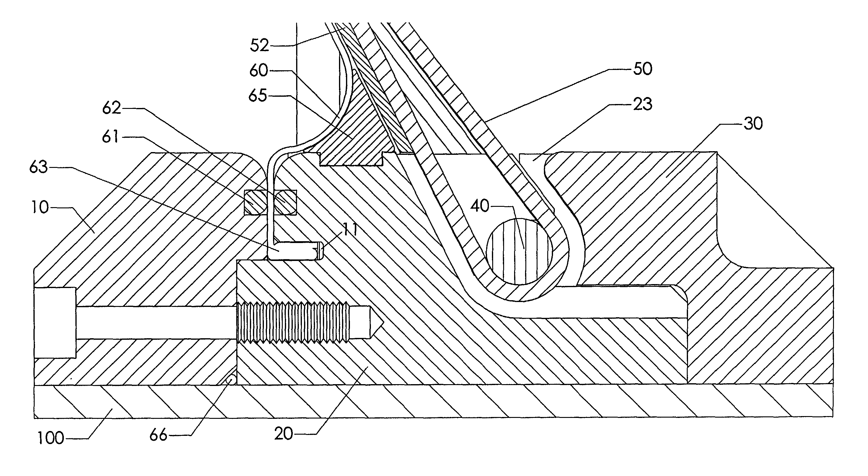
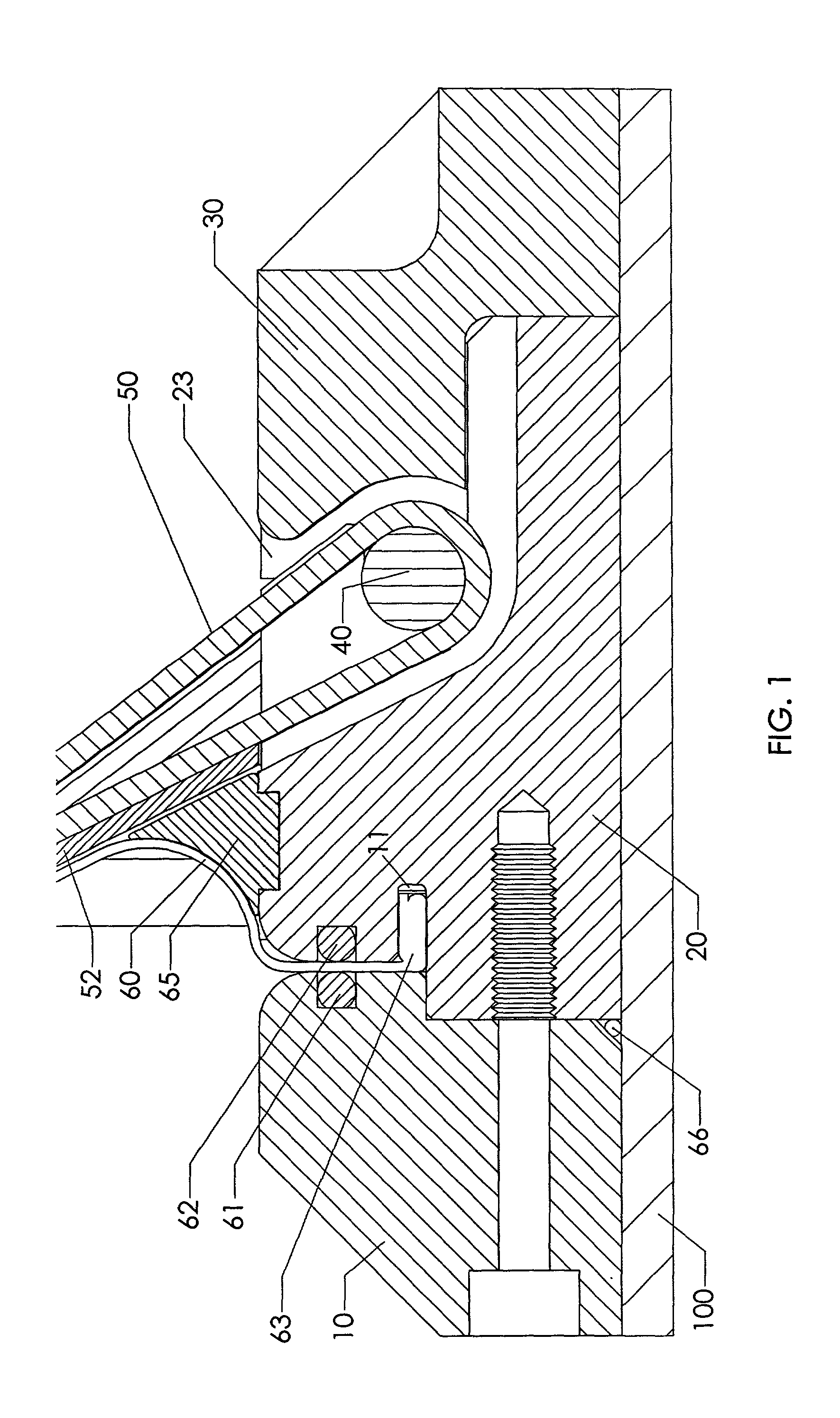
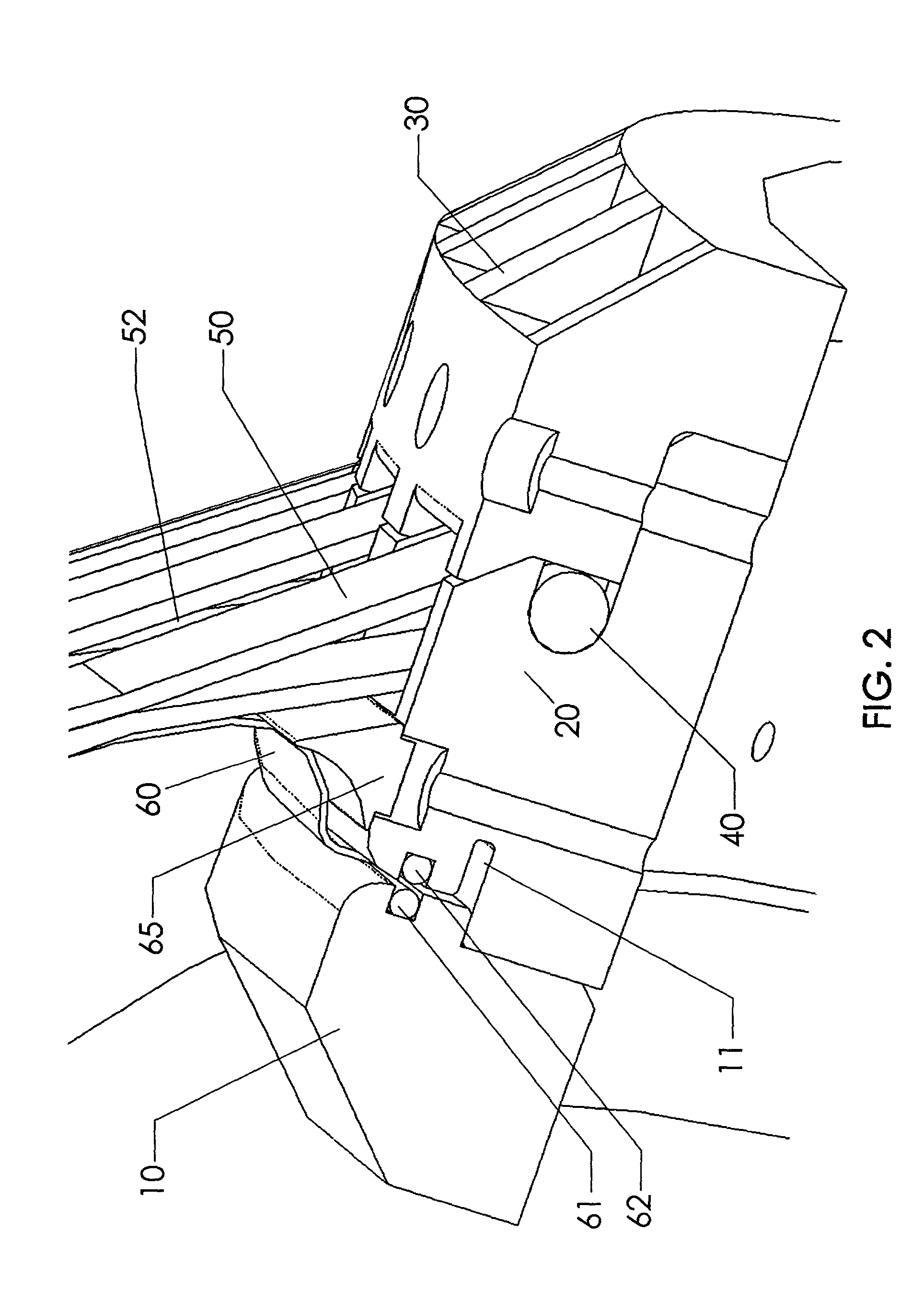
[0030]Preferred embodiments of the present invention that illustrate the best modes now contemplated for placing the invention in practice are described as follows, and in conjunction with the attached drawings that form a part of this specification. The preferred embodiments are described in detail without attempting to show all of the various forms and modifications in which the present invention may be embodied. The preferred embodiments described are illustrative, and as will become apparent to those skilled in the arts, can be modified in numerous ways within the spirit and scope of the invention, the invention being measured by the appended claims and not by the details of the specification.

[0031]The present invention is a restraint and sealing system for use in inflatable space structures that utilizes a flexible, non-rigid pressure boundary. Examples of the construction techniques utilized in the development of these inflatable space structures is provided in Deployable Luna...


PUM


Abstract

The present invention provides a sealing and restraint apparatus to establish a pressure boundary for inflatable or expandable spacecraft. The apparatus is capable of connecting the flexible pressure boundary of an inflatable spacecraft to the rigid structure of the spacecraft. The flexible pressure boundary of the present invention comprises a gas membrane and a restraint layer. The gas membrane minimizes air leakage. The restraint layer carries the forces created by the internal pressurization of the spacecraft. This apparatus provides a hermetic seal and the structural integrity necessary to resist internal pressurization forces.

Description

BACKGROUND OF THE INVENTION[0001]1. Field of the Invention[0002]The present invention relates to the field of seal and restraint systems for the establishment of a pressure boundary on inflatable or expandable structures in a vacuum environment. In particular, the present invention relates to the establishment of a pressure boundary between the flexible and the rigid materials of construction utilized on inflatable spacecraft such as orbiting satellites, space stations, and space vehicles, or any other type of space habitat.[0003]2. Discussion of the Prior Art[0004]Inflatable structures for use in space applications utilize flexible, non-rigid materials of construction to develop and maintain an inflatable pressure boundary over a substantial portion of their structure. Augmenting these non-rigid materials of construction are rigid materials that are necessary to form such components as hatches and docking mechanisms. A long-standing problem has been the development of a means to co...

Claims


Application Information

Patent Timeline
IPC IPC(8): B64G1/52
CPCB64G1/52B64G2001/224B64G1/2227
Inventor MEZITS, JOHNCOMMON, RUSSELL J.RUSI, JOHN A.
Owner BIGELOW DEV AEROSPACE DIVISON L L C NEVADA
Why Eureka
Eureka Blog
Learn More