
Screw extruder and gear pump arrangement for highly viscous media

a technology of high viscosity and gear pump, which is applied in the direction of machines/engines, liquid fuel engines, positive displacement liquid engines, etc., can solve the problems of unsuitable pump, unclean type of gear pump, and unsuitable pump for delivering high viscous media, etc., to build up the pilot pressure and build up the pressure. good, short design

Inactive Publication Date: 2005-12-13
TKH DEUTSCHLAND GMBH & CO KG
View PDF5 Cites 7 Cited by
  • Summary
  • Abstract
  • Description
  • Claims
  • Application Information

AI Technical Summary

Benefits of technology

[0015]The present invention provides a screw extruder and gear pump arrangement in which the gear pump is constnucted in principle so as to correspond with an epicyclic gearbox and, in a particular way, is suitable for delivering highly viscous media such as plastic melts and rubber mixtures. The present invention has the advantage of extensive self cleaning, since the medium to be delivered can be fed in without a significant pilot pressure.
[0040]A particularly advantageous use of the planet gear pump results in a screw extruder in particular for processing rubber mixtures if, downstream of the gear pump, there is an extruder pin cylinder region, such as is disclosed for example by DE-40 39 942 A1, U.S. Pat. No. 4,127,741; the disclosure of which is hereby incorporated by reference. Therein, the planet gear pump can easily build up the high pilot pressure which is advantageous for the extruder pin cylinder region.

Problems solved by technology

Such a pump is basically unsuitable for delivering highly viscous media, since it needs to be fed with a considerable pilot pressure and thus would not be self cleaning.
Because of the small diameters of the bores and the small cross-sectional areas of the inlet and outlet openings, such a pump would be unsuitable for delivering highly viscous media and would not be self cleaning.
This type of gear pump is not self cleaning.
Therefore, when the respective material to be processed is changed, such pumps require complicated dismantling and cleaning work in order not to accept any quality losses following the material change.

Method used


Image

  • Screw extruder and gear pump arrangement for highly viscous media
  • Screw extruder and gear pump arrangement for highly viscous media
  • Screw extruder and gear pump arrangement for highly viscous media

Examples


Embodiment Construction

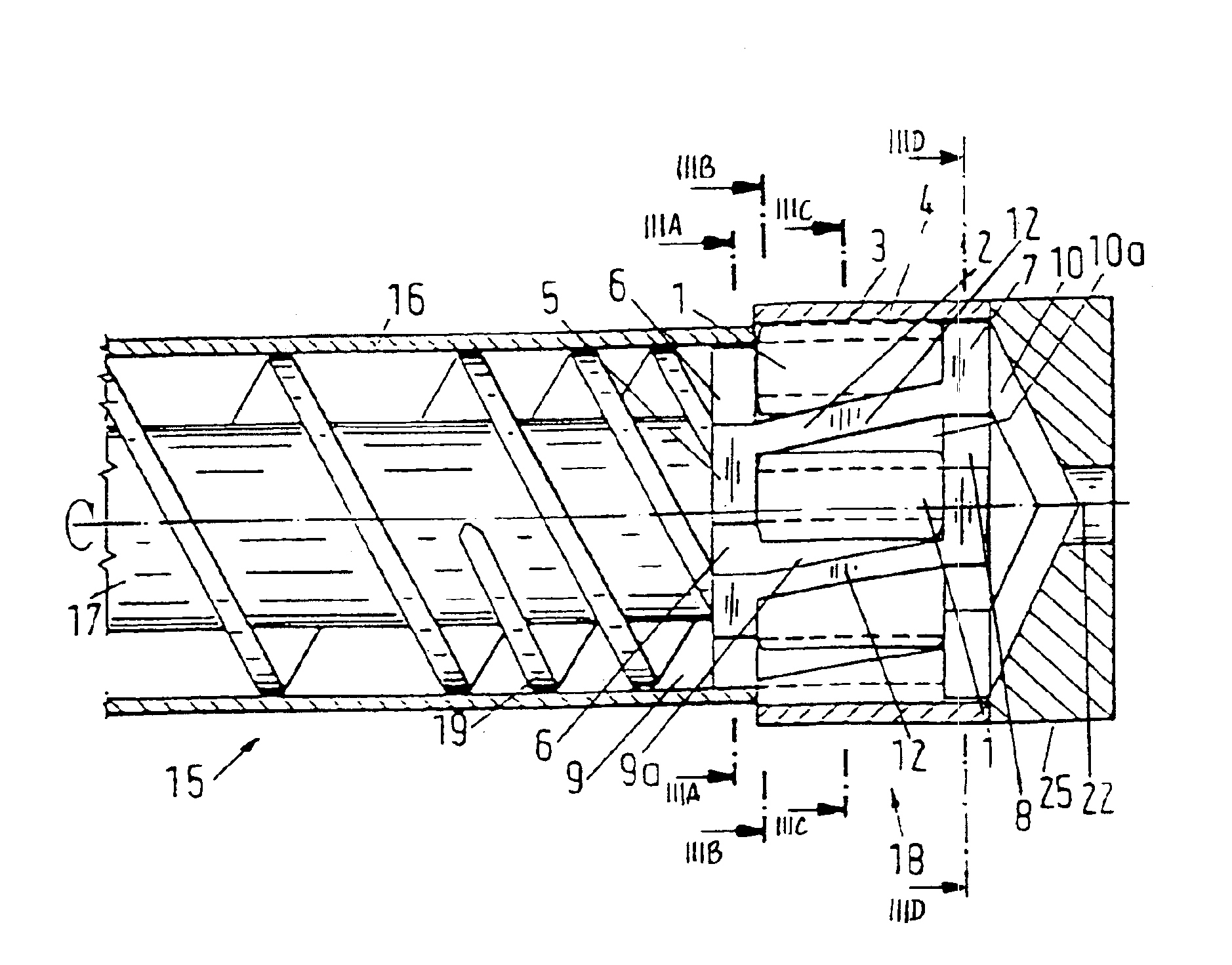
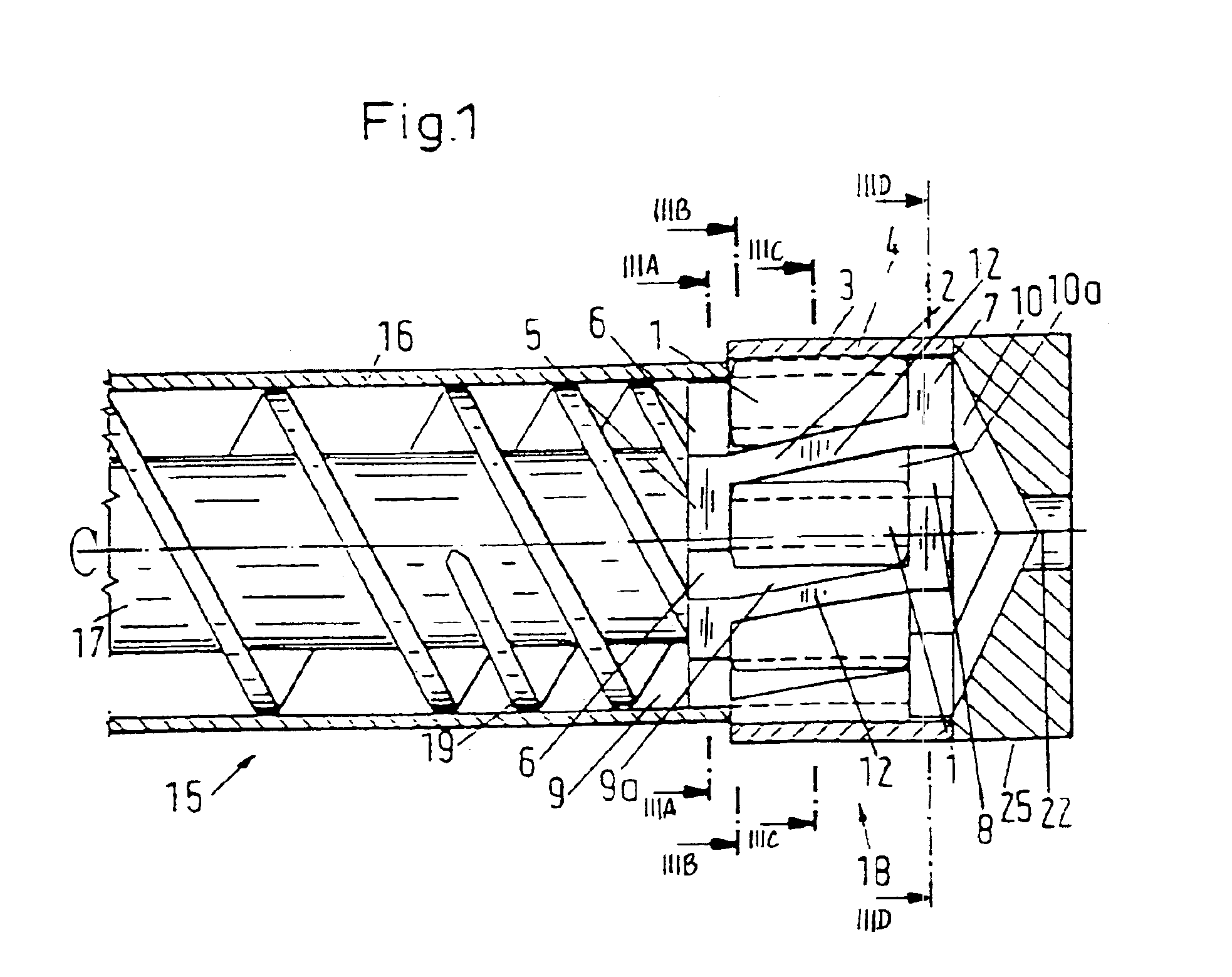
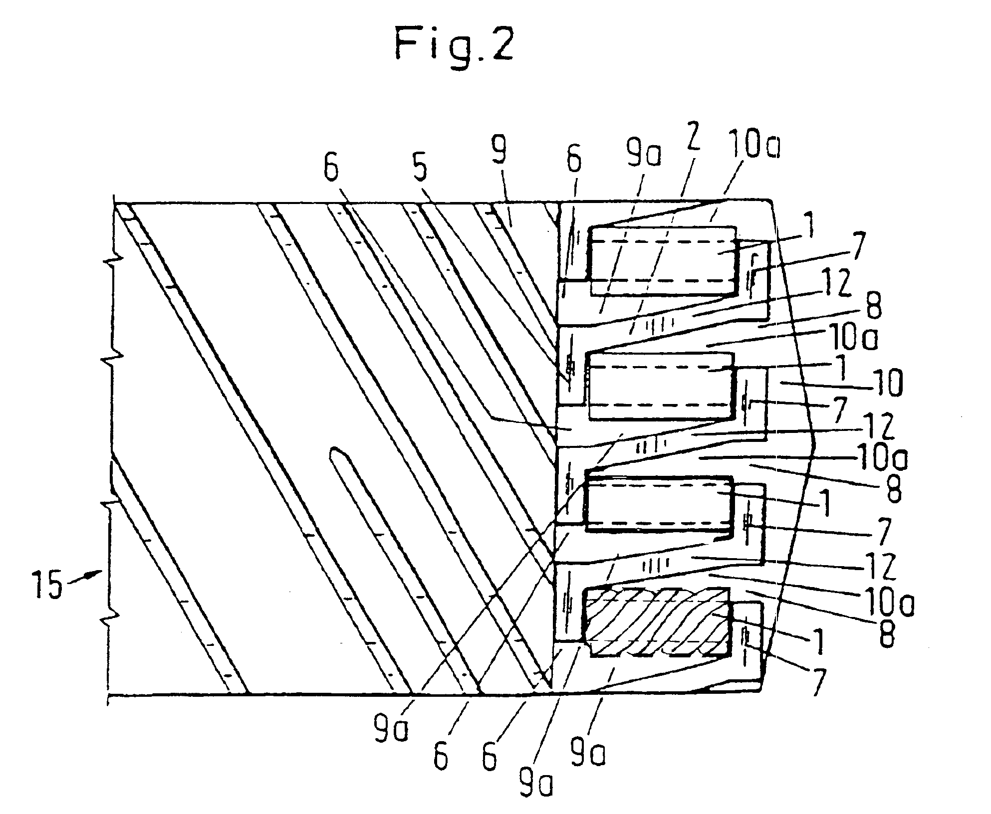
[0051]In FIGS. 1 to 3d, a screw extruder 15 is illustrated in an axial longitudinal section, a number of cross-sectonal views and a schematic embodiment (FIG. 2). The screw extruder 15 has a screw shaft 17 which, viewed in the delivery direction, is initially of two-tum design and at the delivery end 19 has twice the number of turns, i.e. four turns. The screw shaft 17 is surrounded by an extruder casing 16.

[0052]Immediately following the delivery end 19, a planet gear pump 18 is provided, which has a substantially cylindrical pump casing 4, within which a planet carrier 2 with four planet gears 1 rotatably mounted therein is arranged. Provided in the region of the wall of the pump casing 4, on the inside, is a toothed internal gear 3 which, in accordance with one embodiment of the present invention, is designed in one piece with this part of the pump casing 4. On the left-hand side of the planet gears 1 there is an inlet sealing wall 5, which is mounted in a sealed and rotatable ma...


PUM

PropertyMeasurementUnit
viscousaaaaaaaaaa
lengthaaaaaaaaaa
circumferenceaaaaaaaaaa

Abstract

A screw extruder and gear pump arrangement for highly viscous media includes a screw shaft and a gear pump operatively coupled to the screw shaft. A planet carrier is operatively engaged with at least one rotatably mounted planet gear, a first functional element that is cooperatively engaged with planet gear as a sun wheel, and a second functional element that is cooperatively engaged with the planet gear as an outer ring. One of the first functional element or the second functional element includes gear teeth for meshing with the planet gear and the other includes a sealing region for bearing in a sliding and sealing manner over part of the circumference and length of the planet gear. A pump casing surrounds the planet carrier.

Description

CROSS REFERENCE TO RELATED APPLICATIONS[0001]This a U.S. national stage of application No. PCT / DE01 / 03801, filed on Sep. 28, 2001. Priority is claimed and to the following applications: DE 100 49 730.6 filed Sep. 28, 2000 in Germany, and DE 100 58 918.9 filed Nov. 21, 2000 in Germany.BACKGROUND OF THE INVENTION[0002]1. Field of the Invention[0003]The invention relates to a screw extruder and gear pump arrangement for highly viscous media.[0004]2. Description of the Prior Art[0005]Published German Patent Application DE-A 21 00 403 discloses a hydraulic pump which, in the form of an epicyclic gearbox, is equipped with a sun gear, a plurality of planet gears rotatably mounted on a planet carrier and an internal gear, all the gears having teeth. Between the planet gears and the internal gear, which intermesh, and also between the planet gears and the sun gear, which likewise intermesh, suction and pressure chamber elements are formed alternately, being sealed off by arcuate dividing wal...

Claims


Application Information

Patent Timeline
Patent Type & Authority Patents(United States)
IPC IPC(8): B29C48/395B29C48/365B29C48/38B29C48/58B29C48/64B29C48/67B29K21/00
CPCB29C47/367B29C47/38B29C47/404B29C47/60B29C47/605B29C47/627B29C47/64B29C47/364B29C47/667B29C47/6012B29C47/62B29C47/0009B29C48/03B29C48/37B29C48/387B29C48/395B29C48/404B29C48/565B29C48/64B29C48/655B29C48/67B29C48/687B29C48/58B29B7/7495B29B7/86B29B7/428B29B7/429
Inventor UPHUS, REINHARD
Owner TKH DEUTSCHLAND GMBH & CO KG
Learn More