Methods and apparatus for process, factory-floor, environmental, computer aided manufacturing-based or other control system with unified messaging interface

a technology of unified messaging and control system, applied in the field of digital data processing, can solve the problems of requiring special-purpose programs, providing only limited interfaces, and rudimentary workflow definition, and achieve the effects of facilitating communication, enhancing messaging, and enhancing operator response transmission

Inactive Publication Date: 2005-12-13
SCHNEIDER ELECTRIC SOFTWARE LLC
View PDF9 Cites 80 Cited by
  • Summary
  • Abstract
  • Description
  • Claims
  • Application Information

AI Technical Summary

Benefits of technology

[0022]Still other aspects of the invention provide improved methods and apparatus of workflow definition and processing with enhanced messaging. This facilitates communication with an operator station during workflow execution.
[0023]Related aspects of the invention provide such methods and apparatus in which both message content and formatting is transmitted between a workflow processing engine and an operator interface, e.g., via a markup language. Related aspects of the invention provide for use of XML and XSL for these purposes. Still further related aspects provide for customizable display of operator interfaces via controls which execute style sheets. Yet still further related aspects of the invention provide for enhanced transmittal of operator responses to the workflow processing engine.

Problems solved by technology

However, those solutions provide for only rudimentary workflow definition and require special-purpose programs to model plant operations of complexity.
The conventional solutions, moreover, provide only limited interfaces, accepting data from and outputting data to only specific hardware devices and software applications.

Method used


Image

  • Methods and apparatus for process, factory-floor, environmental, computer aided manufacturing-based or other control system with unified messaging interface
  • Methods and apparatus for process, factory-floor, environmental, computer aided manufacturing-based or other control system with unified messaging interface
  • Methods and apparatus for process, factory-floor, environmental, computer aided manufacturing-based or other control system with unified messaging interface

Examples


Embodiment Construction

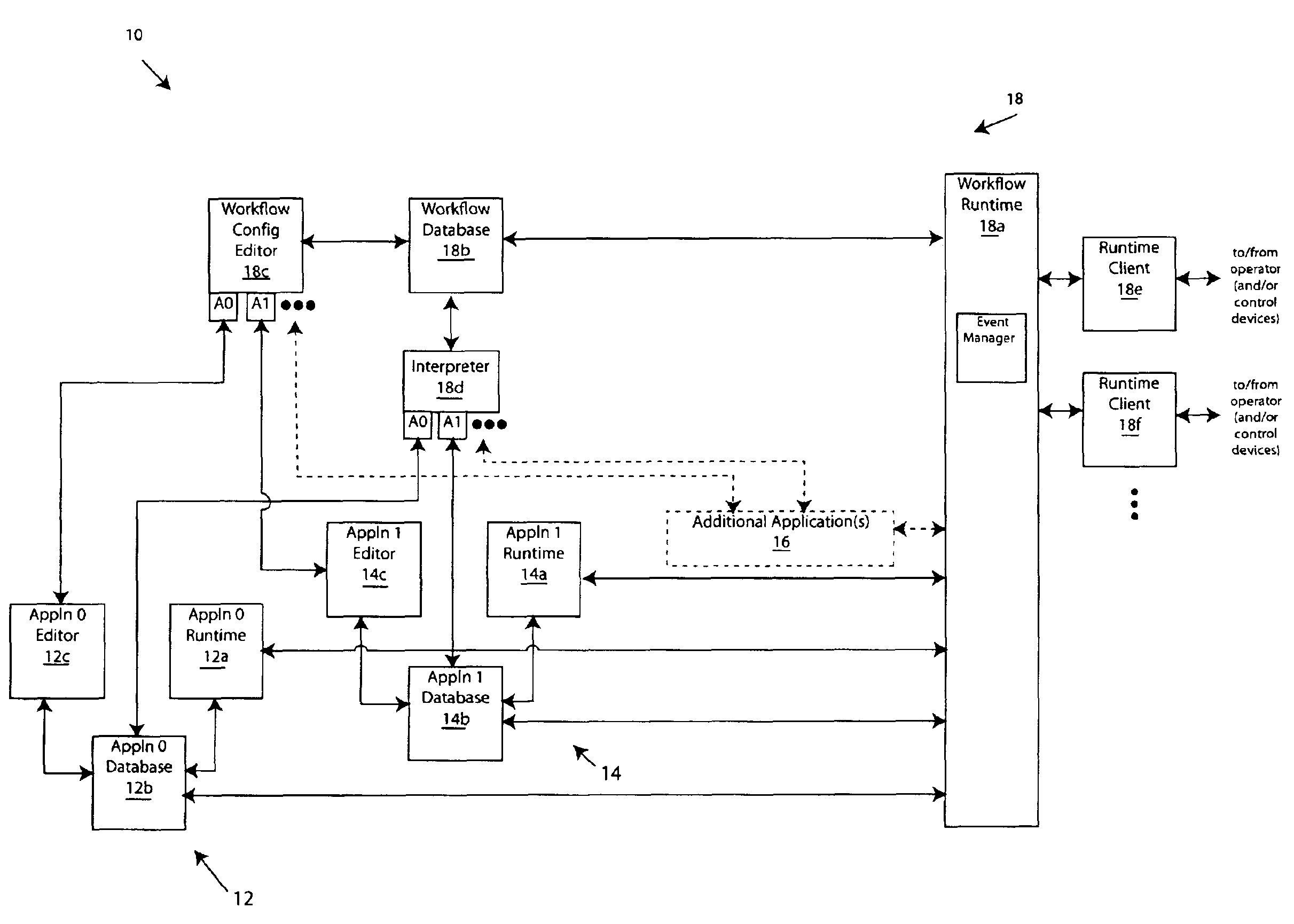
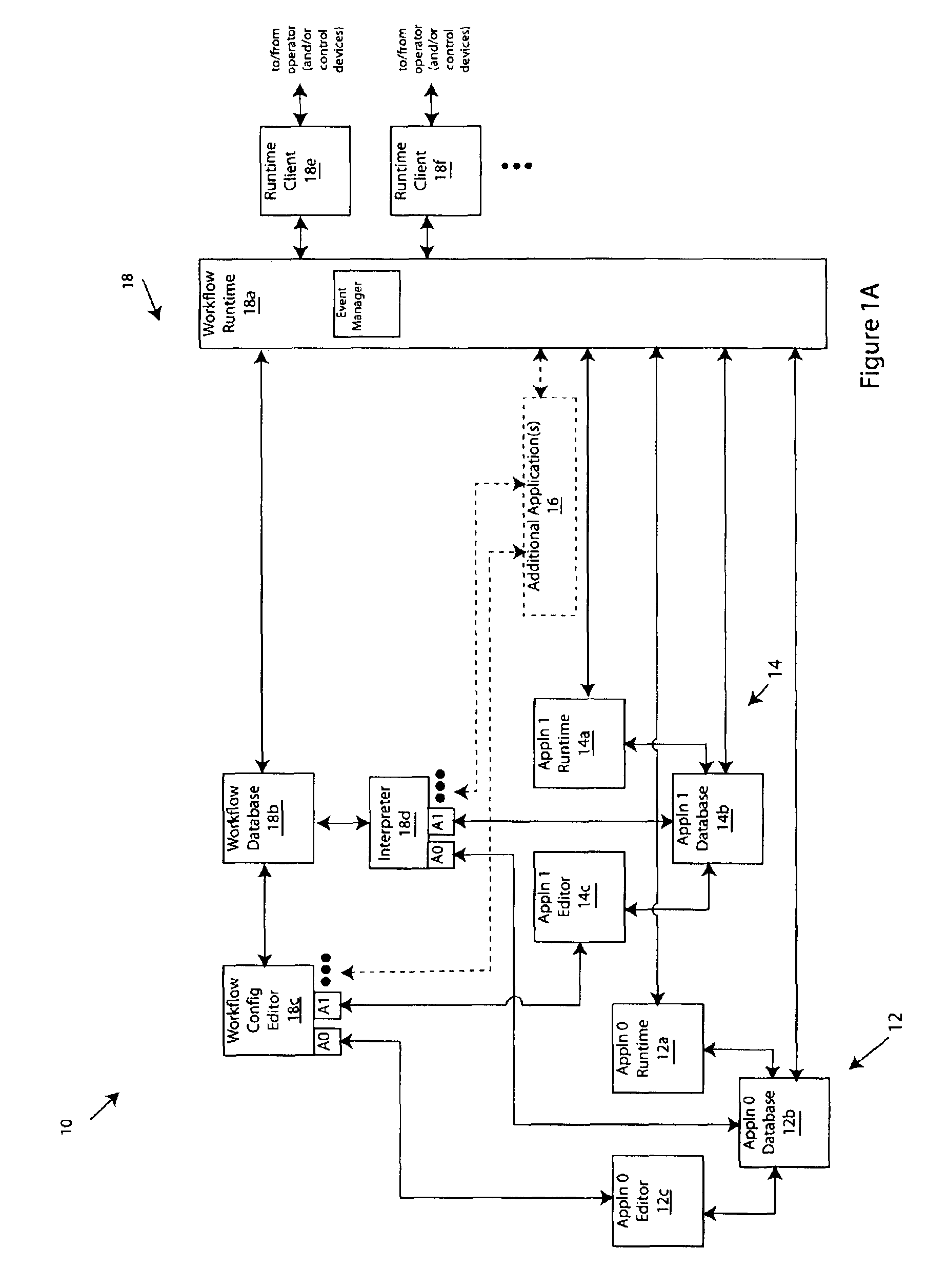
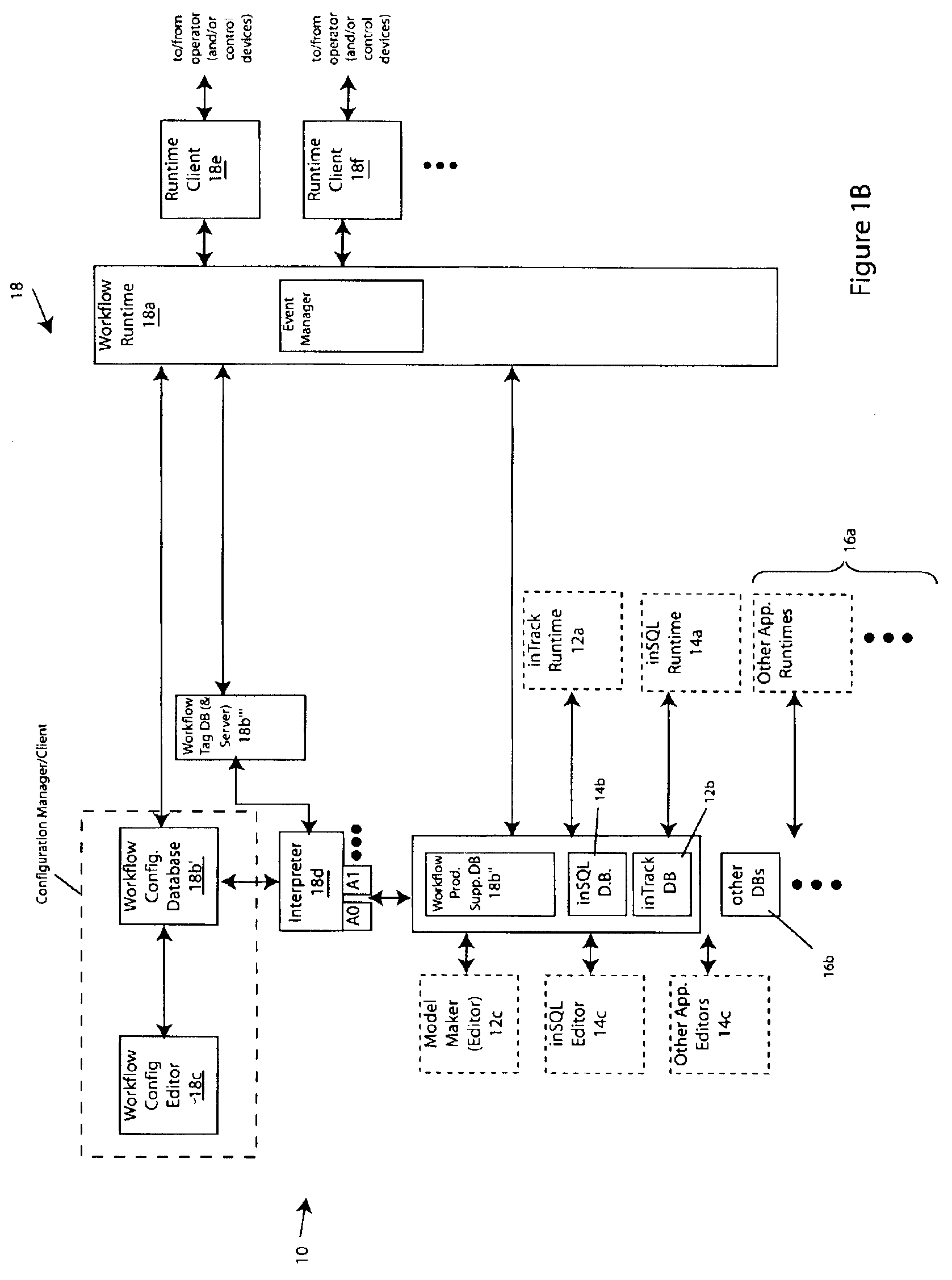
[0062]FIG. 1A depicts a digital data processing system 10 according to one practice of the invention. The illustrated system includes one or more applications 12, 14, 16 of the type commercially available and conventionally used for process, batch, discrete, environmental or other control in manufacturing, utilities or other industries, research or other applications. The applications 12-16 are adapted to monitor and / or control the respective process, batch, environment, and so forth, via sensors and / or control equipment in the conventional manner known in the art. The illustrated system also includes a production engine 18 that is coupled to applications 12-16 and coordinates data collection, operation, and / or reporting thereby.

[0063]Engine 18 and applications 12-16 may execute on a single digital data processing device or multiple digital data processing devices, which may be disposed locally or remotely with respect to one another and which may communicate via network or otherwis...


PUM


Abstract

The invention provides improved methods and apparatus for workflow editing. Such methods and apparatus permit, for example, user-defined and/or other tasks to be combined in any combination or combinations to specify a workflow. The tasks can be linked for direct, serial processing and/or for conditional processing that includes branching and/or looping. The invention also improved methods and apparatus of workflow definition and processing with extensible actions. The invention provides, further, improved methods and apparatus for workflow definition and processing which utilize workflow variables for communication of data and control information among tasks within a workflow. The invention provides, still further, improved methods and apparatus of workflow definition and processing with enhanced messaging. The invention provides, still yet further, improved methods and apparatus for workflow definition and processing which permit definition of hierarchically enumerated data types and for for definition of “plans” to collect, e.g., for storage, data such as the aforementioned hierarchical data types.

Description

[0001]This application claims the benefit of filing of U.S. Provisional Patent Application No. 60 / 372,770, filed Apr. 15, 2002, and entitled METHODS AND APPARATUS FOR WORKFLOW DEFINITION AND PROCESSING, the teachings of which are incorporated herein by reference.BACKGROUND OF THE INVENTION[0002]The invention pertains to digital data processing and, more particularly, by way of non-limiting example, to automated workflow definition and processing. The invention has application, for example, in process control, environmental control, computer aided manufacturing, and other industrial and non-industrial applications.[0003]Automated workflow processing is increasingly common in today's manufacturing plants. Conventional solutions provide general capabilities for interfacing plant equipment to identify events and take specific responsive actions. However, those solutions provide for only rudimentary workflow definition and require special-purpose programs to model plant operations of com...

Claims


Application Information

Patent Timeline
Patent Type & Authority Patents(United States)
IPC IPC(8): G05B15/00G05B19/418G06F7/00G06F19/00G06Q10/10
CPCG05B19/41865G05B19/41885G06Q10/10G06Q10/107G05B2219/31342G05B2219/31449G05B2219/32128G05B2219/32424Y10S715/967Y10S715/965Y02P90/02Y02P90/80
Inventor DEREMER, ROBERT A.GROVE, ERIC P.GRUBB, LORIN V.HALLQUIST, JR., ROBERT D.LEMERT, PAUL W.MUNDORF, EDWARD R.WEINRICH, STEVEN M.WRIGHT, JULIA
Owner SCHNEIDER ELECTRIC SOFTWARE LLC
Why Eureka
Try Eureka