Steam engine

a steam engine and steam technology, applied in steam engine plants, steam accumulators, machines/engines, etc., can solve the problems of large heat loss in steam engines, high heat loss in heating devices, and related parts or elements, which are opposed to high-temperature and high-pressure steam, and achieve reduced time for heating and vaporizing working fluid, reduce heat loss, and reduce the effect of tim

Inactive Publication Date: 2005-12-20
DENSO CORP
View PDF6 Cites 12 Cited by
  • Summary
  • Abstract
  • Description
  • Claims
  • Application Information

AI Technical Summary

Benefits of technology

[0011]It is, therefore, an object of the present invention, in view of the above mentioned problems, to provide a steam engine in which a working fluid is filled into a fluid container and kinetic energy is obtained by moving (back and forth) the working fluid in the fluid container as a result of heating and cooling the fluid, so that an efficiency of generating the steam by a heating device is improved and heat loss is reduced.
[0016]According to the steam engine designed as above, almost all of the working fluid flowing into the flow passage can be vaporized, and thereby the (liquid-phase) working fluid entering into the flow passage of the heating device is prevented from flowing toward the cooling device after having absorbed heat (without being vaporized) from the heating device. As a result, heat loss caused by the working fluid, which has not been vaporized at the heating device, can be reduced and the steam engine having a high efficiency can be realized.
[0017]According to another feature of the invention, the flow passage of the heating device is formed of multiple through-holes, through which the working fluid flows, and a diameter of each through-hole is made almost equal to or smaller than a depth of heat penetration “δ”. According to such an arrangement, a time for heating and vaporizing the working fluid can be reduced.
[0018]According to a further feature of the present invention, the heating device is arranged at a vertically higher position than the cooling device. According to such an arrangement, the vaporized steam generated by the heating device pushes down a liquid surface (which is a boundary between the vaporized steam and the liquid-phase working fluid) toward the cooling device, and the steam reaching the cooling device is cooled and condensed. Accordingly, the working fluid moves in the fluid container in a back and forth direction (in an upward and downward direction) with a self-excited vibration. Furthermore, a time for heat exchange between the working fluid and the heating device or the cooling device can be made longer, to thereby improve an operational efficiency of the steam engine.
[0019]According to a still further feature of the present invention, a gas is filled in the fluid container as a vibration generating means for periodically applying a vibrating force (a compressive reaction force) to the working fluid, so that the operational efficiency of the steam engine can be further improved.

Problems solved by technology

The related parts or elements, such as the pistons, which are opposed to the high-temperature and high-pressure steam, are likely to be deteriorated.
And thereby, it is disadvantageous in that a heat loss would become large in the heating device.
As a result, since the latter working fluid is cooled down by the cooling down without contributing in generation of the kinetic energy, the large heat loss may occur in such steam engine.

Method used


Image

  • Steam engine
  • Steam engine
  • Steam engine

Examples


first embodiment

(First Embodiment)

[0030]A first embodiment of the present invention will now be explained with reference to the drawings.

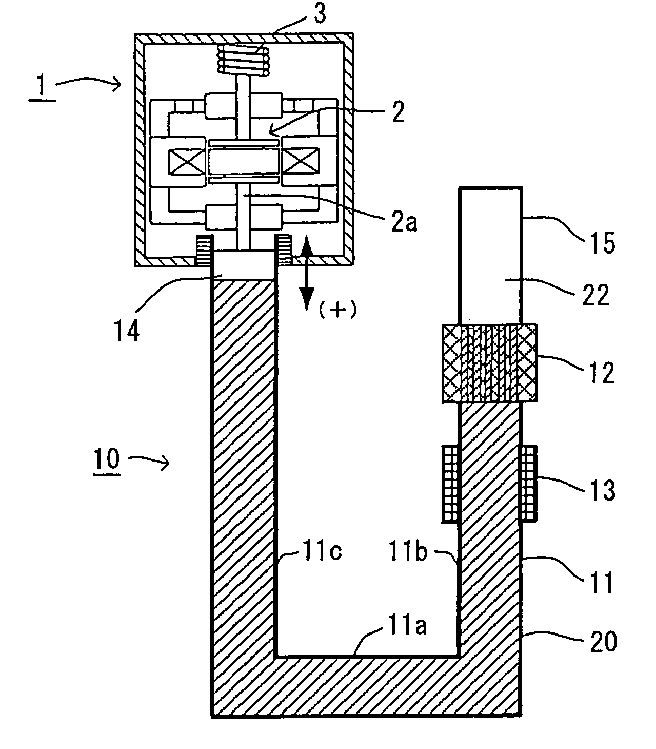
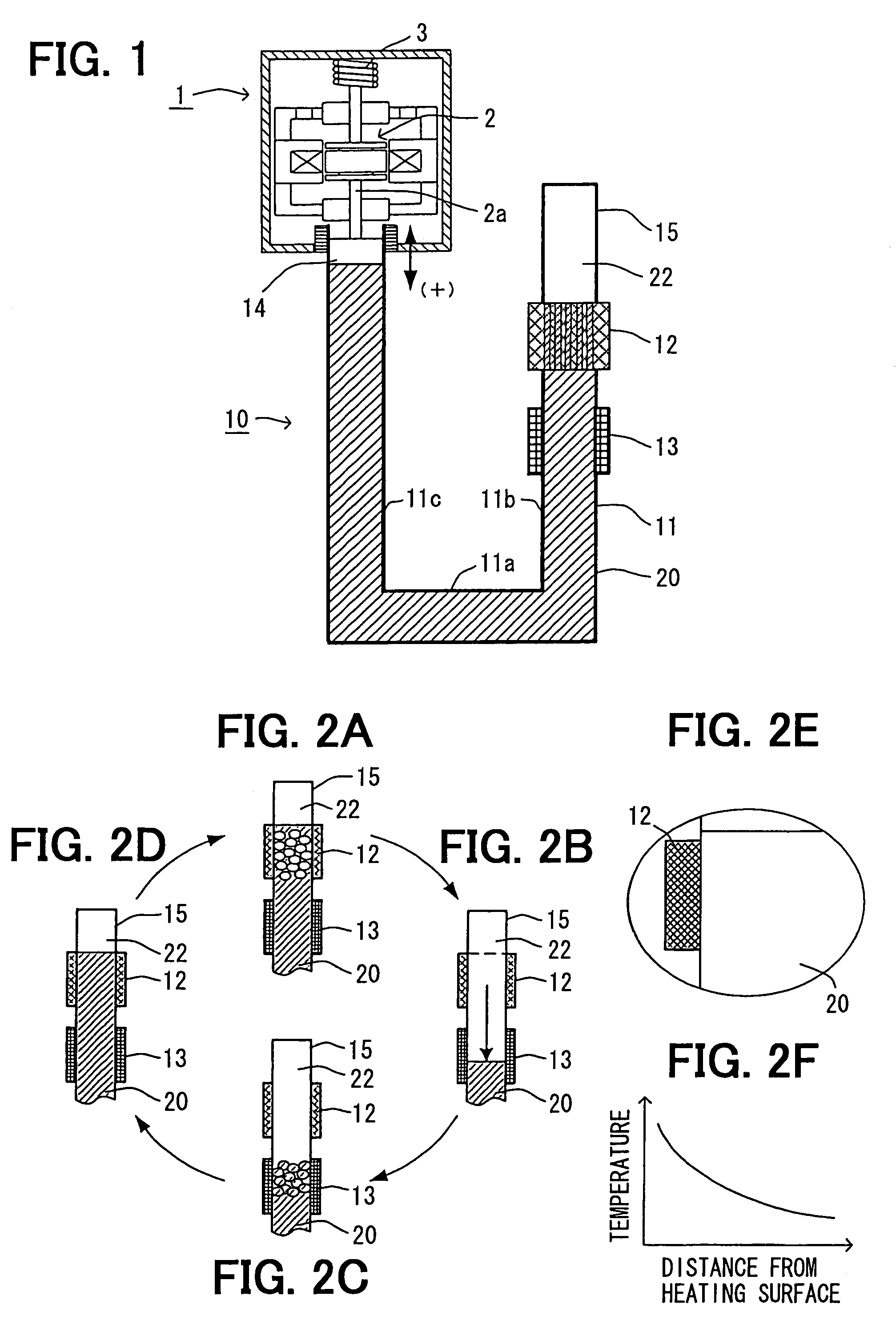
[0031]In the first embodiment, a steam engine is applied to a linear motor for displacing a moving element 2 in an electric power generator 1. FIG. 1 is a schematic view showing the steam engine 10 and the electric power generator 1 according to a first embodiment of the present invention.

[0032]The electric power generator 1 is a linear vibration actuator for generating electromotive force by displacing the moving element 2, in which a permanent magnet is embedded.

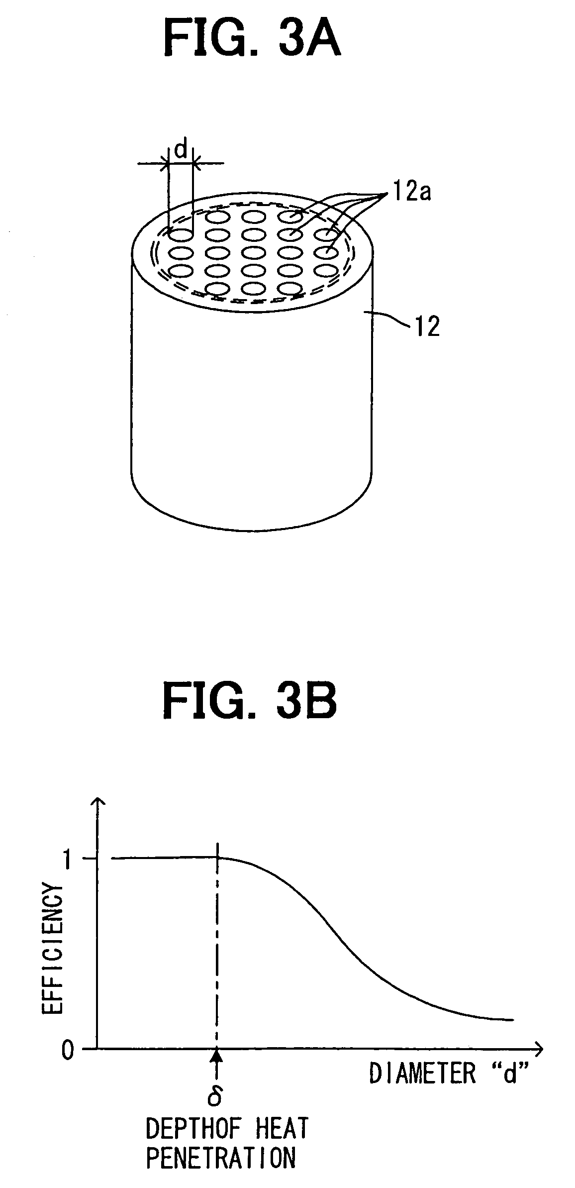
[0033]As shown in FIG. 1, the steam engine 10 has a fluid container 11 in which working fluid 20 is filled and the working fluid 20 can freely move (flow) therein, a heating device 12 for heating the fluid in the fluid container 11, and a cooling device 13 for cooling steam heated and vaporized by the heating device 12.

[0034]The fluid container 11 is preferably made of a heat insulating material, except ...

second embodiment

(Second Embodiment)

[0055]A second embodiment of the present invention is explained with reference to FIG. 4, showing a schematic view of a power generating apparatus according to the second embodiment of the present invention.

[0056]As shown in FIG. 4, the power generating apparatus comprises the electric power generator 1 and the steam engine 10, as in the same manner to the first embodiment, wherein the second embodiment differs from the first embodiment in that another pipe portion 11d is added to the first pipe portion 11b to form a circular pipe portion, a displacer 30 is provided above the heating device 12, an inert gas 22 is filled in the pipe portion below the displacer 30, the working fluid 20 is also filled in the other pipe portion 11d, and the displacer 30 is operated by a driving circuit 34.

[0057]The displacer 30 comprises a movable element 30a for closing an inside fluid passage of the circular pipe portion (11b, 11d) at a position above the heating device 12, and an a...


PUM


Abstract

A steam engine has a fluid container, a heating device and a cooling device provided at the fluid container for heating and cooling working fluid filled in the fluid container, so that a part of the working fluid is heated and vaporized to move the liquid-phase working fluid in one direction. When the vaporized steam is cooled and liquidized, the pressure of the working fluid in the fluid container is decreased, to thereby move the liquid-phase working fluid in the backward direction. Kinetic energy is thereby generated by using the back and forth movement of the working fluid. The heating device has multiple through-holes, through which the working fluid flows and heated by a heating surface (an inner surface of the through-holes) of the heating device, wherein a diameter “d” of the through-hole is made almost equal to or smaller than a depth of heat penetration “δ”, which is determined by the following formula:δ=√{square root over (2a / ω)}wherein “a” is a heat diffusivity of the working fluid, and“ω” is an angular frequency of the working fluid during the working fluid is periodically moved back and forth.

Description

CROSS REFERENCE TO RELATED APPLICATION[0001]This application is based on Japanese Patent Application No. 2004-062501 filed on Mar. 5, 2004, the disclosure of which is incorporated herein by reference.[0002]1. Field of the Invention[0003]The present invention relates to a steam engine for converting heat energy into kinetic energy.[0004]2. Background of the Invention[0005]A steam engine is known in the art, for example as disclosed in Japanese Patent Publication No. S58-57014. In the conventional steam engine as above, a working fluid is filled into a fluid container, the fluid is heated and vaporized by a heating device, and the vaporized steam is then cooled and condensed to change a pressure in the fluid container, so that kinetic energy is obtained by the pressure change in the fluid container.[0006]In the above conventional steam engine, pistons or the like in the fluid container are moved by the steam generated by the heating device, to generate the kinetic energy. The related ...

Claims


Application Information

Patent Timeline
Patent Type & Authority Patents(United States)
IPC IPC(8): F01K13/00F01B29/12F03G7/00
CPCF01K25/02F03G7/00
Inventor YATSUZUKA, SHINICHIODA, SHUZOKOMAKI, KATSUYA
Owner DENSO CORP
Why Eureka
Try Eureka