Stereoendoscope wherein images having passed through plural incident pupils are transmitted by common relay optical systems

a relay optical system and endoscope technology, applied in the field of endoscopes, can solve the problems of large magnification difference between the right and left images, large focusing position, and large respective parts

Inactive Publication Date: 2005-12-20
OLYMPUS CORP
View PDF20 Cites 66 Cited by
  • Summary
  • Abstract
  • Description
  • Claims
  • Application Information

AI Technical Summary

Benefits of technology

[0018]When thus formed, as the objective optical system has plural independent incident pupils, irrespective of the size of the diameter of the incident pupil of the objective optical system, the parallax will be able to be made large. Also, as the plural images and pupils are not separately transmitted by the plural transmitting systems but are transmitted by the common image transmitting optical system, the number of parts will be able to be reduced. Even if a production error is present in the individual image transmitting optical system, as the images are transmitted by the common image transmitting system, the variation between the plural transmitted images will be able to be reduced.
[0022]In this formation, as the operation common to (a) and (b) is made and the image transmitted by the image transmitting optical system is also spatially separated, the image can be stereo-inspected through an image taking means taking images or an ocular optical system making observation with the naked eyes. The image taking means can use one or more image taking devices and can take plural images transmitted and spatially separated by the transmitting optical system and stereo-inspection is thereby possible.

Problems solved by technology

Also, the magnification difference between the right and left images due to the errors of the respective parts is large, the displacement of the focusing position is large, the normal stereo-inspection can not be made and therefore a fine adjustment is necessary.
On the other hand, when compared with the same thickness, the magnitude of the parallax will be smaller than in the first type and a sufficient stereo-feel will be hard to obtain.
That is to say, there is a problem that the center distance between the right and left incident pupils is hard to make large.
Particularly, in case the distal end is thin, no sufficient stereo-feel will be obtained.

Method used


Image

  • Stereoendoscope wherein images having passed through plural incident pupils are transmitted by common relay optical systems
  • Stereoendoscope wherein images having passed through plural incident pupils are transmitted by common relay optical systems
  • Stereoendoscope wherein images having passed through plural incident pupils are transmitted by common relay optical systems

Examples


first embodiment

[0107]As shown in FIG. 5, a stereoendoscope apparatus 1 comprises a stereoendoscope 2 of the first embodiment having an image taking optical system for stereo-inspection built-in, a light source apparatus 3 feeding an illuminating light to an illuminating light transmitting means provided in this stereoendoscope to transmit the illuminating light, a camera controlling unit (abbreviated as a CCU hereinafter) 4 processing signals for an image taking means built-in in this stereoendoscope 2, a scan converter 5 converting the signal from this CCU 4 to a video signal, a color monitor 6 displaying the video signal put out of this scan converter 5 and shutter spectacles 27 having a shutter function for stereo-inspecting the image displayed in this color monitor 6.

[0108]The stereoendoscope 2 has an elongate inserted section 11 to be inserted into a body cavity or the like and a gripped section formed to be large in the diameter at the proximal end of this inserted section so as to be grippe...

second embodiment

[0155]The stereoendoscope apparatus provided with this second embodiment can be realized in substantially the same formation as of the stereoendoscope apparatus 1 in FIG. 5.

[0156]This second embodiment has an advantage that the image taking devices 23a and 23b can be focused respectively independently. If they are precisely adjusted, an image higher in the quality than in the case of a common image taking device 23 will be able to be made.

[0157]Also, the parallax can be made variable the same as in the first embodiment. However, this embodiment has an advantage that, when the left and right image taking devices 23a and 23b are moved as operatively connected with the movement of the objective optical systems 21a and 21b, the movement will not be restricted to be within the image taking range in the case of the common image taking device 23.

[0158]That is to say, in the first embodiment, as the image taking device 23 is common, the moving range of the left and right images 10a and 10b ...

third embodiment

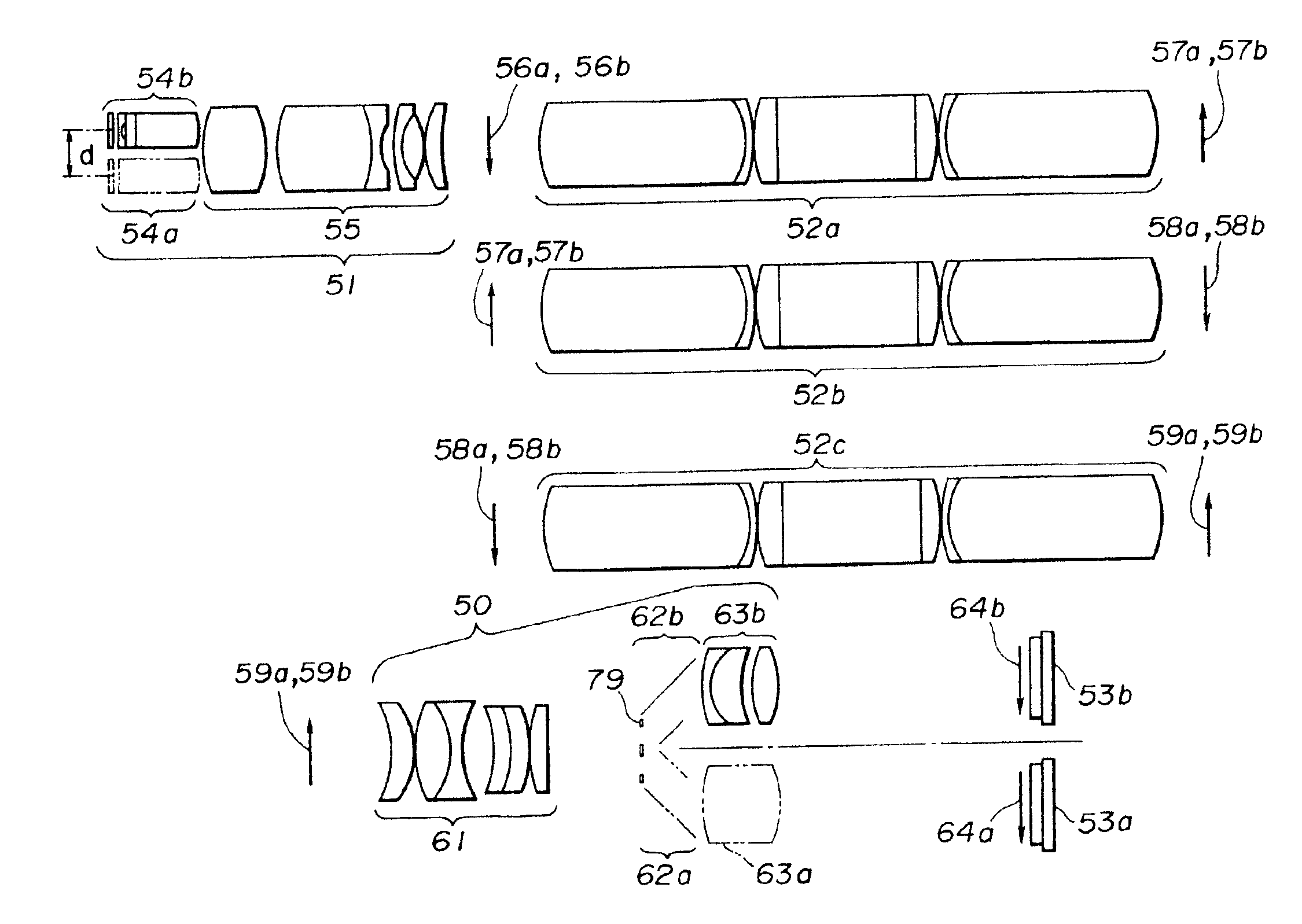
[0164]Therefore, in the third embodiment, as shown in FIG. 9, the light receiving surface is arranged as inclined in conformity with the contact surface of the curved image surface. In FIG. 9, the light receiving surface is inclined by 25.332 degrees to the surface vertical to the optical axis of the relay lens system 22c.

[0165]According to this third embodiment, not only the effects of the second embodiment are retained but also a picture image having little curvature aberration is obtained. By the way, the lens data of the third embodiment are as in Table 2.

[0166]By the way, as the petzval sum of the relay lens systems 22a, 22b and 22c is a positive value, the petzval sum of the objective optical systems 21a and 21b may be made a negative value to control the image surface curvature aberration of the final images 10a and 10b having passed through the relay lens system 22c.

[0167]FIGS. 10A and 10B are of modifications showing this manner.

[0168]As shown in FIG. 10A, the petzval sum...


PUM


Abstract

The illuminating light transmitted by the light guide inserted through the elongate inserted section is projected out of the distal end surface of the inserted section. The illuminated objects pass through the respective pupils of the two objective lens systems arranged in parallel within the distal end section of the inserted section and their images are formed on the focal surface. The respective images are transmitted to the rear side by one common relay lens system. The transmitted final images are formed respectively on the image taking surfaces of the image taking devices. The respective images photoelectrically converted by the respective image taking devices are processed to be signals, are displayed in the monitor and are stereo-inspected through shutter spectacles.

Description

[0001]This application is a divisional of Ser. No. 09 / 053,094 filed Apr. 1, 1998, now U.S. Pat. No. 6,306,082 which is a divisional of Ser. No. 08 / 404,890 filed Mar. 16, 1995 which has issued as U.S. Pat. No. 5,743,846.BACKGROUND OF THE INVENTIONField of the Invention and Description of Related Arts[0002]This invention relates to a stereoendoscope wherein images having passed through plural incident pupils are transmitted by common relay optical systems so that an observation providing a stereo-feel may be possible.[0003]Recently, particularly in the surgical field, there is noted a so-called endoscope operation wherein, in order to reduce the burden on the patient, without opening the abdomen, a small hole is made in the abdominal part, an endoscope is inserted through the hole for the observation and treatment. In this field, the operation has been already made by directly seeing and stereo-observing the affected part with both eyes and therefore, even in the endoscope operation, ...

Claims


Application Information

Patent Timeline
Patent Type & Authority Patents(United States)
IPC IPC(8): A61B1/00G02B23/24
CPCA61B1/00193G02B23/2415
Inventor TAKAHASHI, SUSUMUNAKAMURA, SHINICHITAKEBAYASHI, TSUTOMU
Owner OLYMPUS CORP
Why Eureka
Try Eureka