Hydrogen/oxygen generating system with temperature control

a technology of hydrogen gas and generating system, which is applied in the direction of fuel cell details, climate sustainability, final product manufacture, etc., can solve the problems of gas production operation often stopping, system consumes large amounts of electricity, and unsatisfactory cooling process, so as to reduce the volume required for the electrolytic tank, increase the amount of hydrogen gas generated, and save electricity

Inactive Publication Date: 2005-12-20
CHOU NAI SUNG
View PDF7 Cites 28 Cited by
  • Summary
  • Abstract
  • Description
  • Claims
  • Application Information

AI Technical Summary

Benefits of technology

[0059](1) The use of high voltage, low current electrolysis for hydrogen gas generation can save on electricity use and increase the amount of hydrogen gas generated and reduce the volume required for the electrolytic tank.
[0060](2) The new system allows for quick production of gases namely hydrogen and oxygen and there is no need for a gas storage facility.
[0061](3) The unique setup can generate gas readily on demand. When the system is not being used there is no hydrogen / oxygen gases present therefore resulting in a reliable and safe system.

Problems solved by technology

Systems conventionally used to generate hydrogen and oxygen gases from the electrolysis of water and collect the combined product gases produced in a closed electrolytic chamber have several inherent weaknesses.
Given the design of the electrolytic rods, such a system consumes large amounts of electricity.
Another weakness with conventional systems is in the cooling process which is not ideal because it only uses the cooling effect of a cooling fan to lower the temperature of the electrolytic solution in the electrolytic chamber.
As a result, the gas production operation often stops because of overheating.
A third shortcoming of such a conventional hydrogen-oxygen generating system is that the combustion flame temperature is fixed, and therefore cannot be adjusted to the requirements of different flame temperatures needed for different industrial applications.
Thus, such a conventional system is limited to use in operation scenarios with compatible temperature needs, cooling requirements, and energy usage.
Torches using the fuel gas produced in such units have a very hot flame produced and have no means to adjust the ignition flame temperature.
None of the above-described art combines a liquid coolant process with ignition flame temperature modification.

Method used


Image

  • Hydrogen/oxygen generating system with temperature control
  • Hydrogen/oxygen generating system with temperature control
  • Hydrogen/oxygen generating system with temperature control

Examples


Embodiment Construction

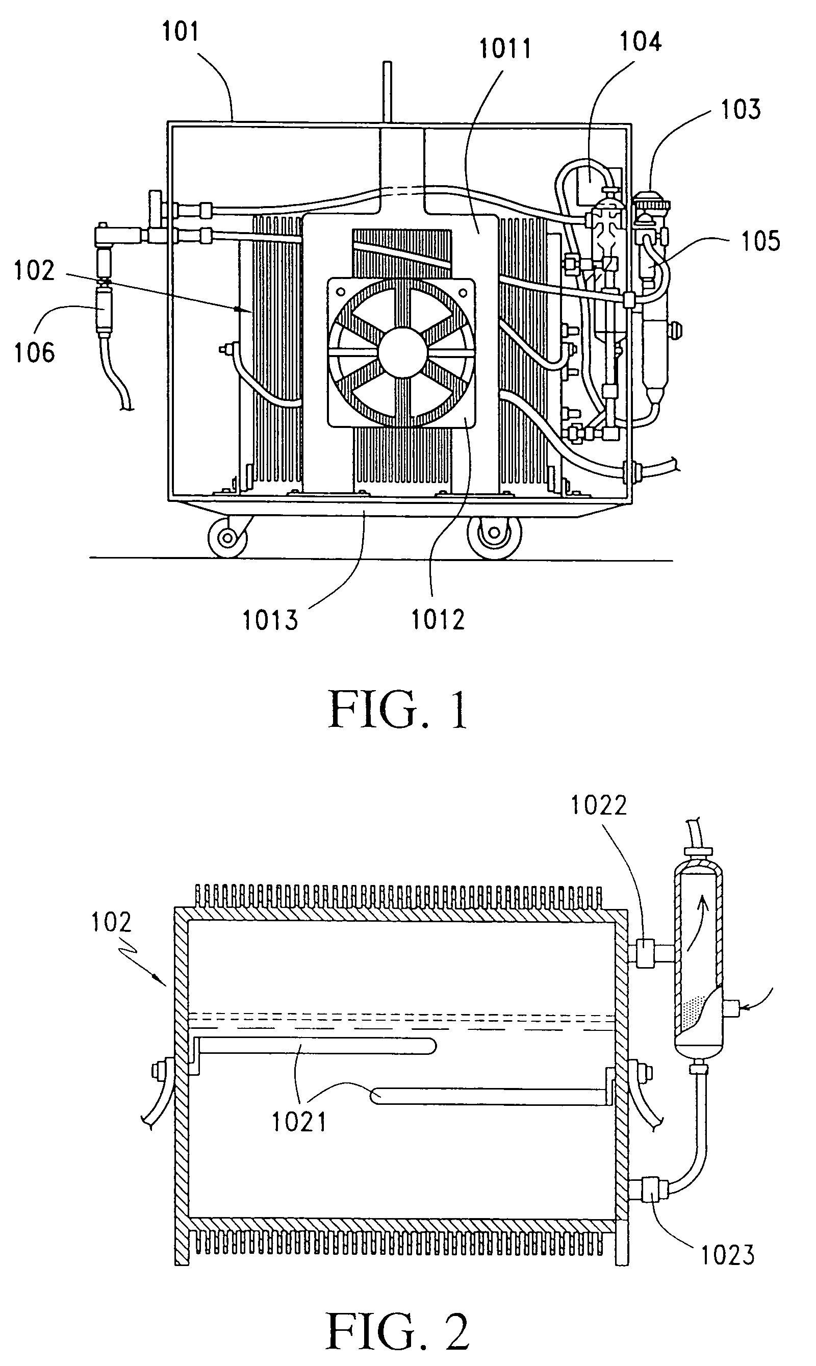
[0070]The conventional mixed hydrogen-oxygen generator shown in FIGS. 1 and 2 includes a generator body framework (101) on which an electrolytic chamber (102) is built. On top of the body frame is a Π-shaped support frame (1011). Inside of the body framework is a cooling fan (1012).

[0071]Electrolytic chamber (102), a sealed hollow structure, is situated at the center of the foundation platform (1013). On both left and right internal sides and not extending inward are (+) (−) electrolytic rods (1021) in contact with electrolytic solution of suitable height. Gas outlet (1022) is situated at the upper part of the sidewall of the electrolytic chamber (102) whereas water inlet (1023) is situated at the lower part. The gas outlet of electrolytic chamber (102) is connected on the outside to a watertight backfire prevention system (103). This watertight backfire prevention system (103) is a hollow tube-like structure located on the outside of generator body frame (101).

[0072]A pressure regu...


PUM

PropertyMeasurementUnit
temperatureaaaaaaaaaa

Abstract

A mixed hydrogen-oxygen fuel generator system uses an electrolytic solution to generate gaseous hydrogen-oxygen fuel through the electrolysis of water. This generator system includes: at least one electrolytic cell with multiple metallic plates used as an internal isolation system in which two of the plates separately connect to both the positive and negative terminal of a DC circuit. These plates are used for the electrolysis of the electrolytic solution in the cell(s) to produce, under pressure, mixed hydrogen-oxygen fuel. The apparatus also includes a cooling system containing a water cooling tank in which there are two zones: one is the electrolytic solution circulation coil and the another is a water circulation zone. The cooler provides the circulating, cooling water used to adjust the temperature of the operating cell and of the electrolyte solution to within a given temperature range in order to ensure that the cell is not affected by excessively elevated temperatures that can stop operations due to cell overheating. Another effect of this cooling system is to precipitate moisture out of the generated gas products. The ignition flame temperature of the gaseous fuel produced can be adjusted for specific applications by passage of the hydrogen/oxygen gas stream through a temperature-control fluid. Thus, continuous 24 hours operation can be achieved along with better gas production efficiency and fuel cell energy generation.

Description

[0001]This application is a continuation application Ser. No. 10 / 644,784, filed Aug. 21, 2003, now U.S. Pat. No. 6,740,436 and claims the priority benefit under 35 U.S.C. section 119 of U.S. Provisional Patent Application No. 60 / 404,917 entitled “Hydrogen-Oxygen Generating System with Temperature Control”, filed Aug. 22, 2002, which is in its entirety herein incorporated by reference.BACKGROUND OF THE INVENTION[0002]Systems conventionally used to generate hydrogen and oxygen gases from the electrolysis of water and collect the combined product gases produced in a closed electrolytic chamber have several inherent weaknesses. Given the design of the electrolytic rods, such a system consumes large amounts of electricity.[0003]Another weakness with conventional systems is in the cooling process which is not ideal because it only uses the cooling effect of a cooling fan to lower the temperature of the electrolytic solution in the electrolytic chamber. As a result, the gas production oper...

Claims


Application Information

Patent Timeline
Patent Type & Authority Patents(United States)
IPC IPC(8): C25B15/02C25C3/16H01MH01M2/04H01M2/08H01M8/02H01M8/04H01M8/06H01M8/08H01M8/18
CPCC25B15/02H01M8/0656H01M8/04029H01M8/186Y02E60/50Y02P70/50
Inventor CHOU, NAI SUNGSUM, CHOI SHIUTE-HUNG, CHOULIN, HUI
Owner CHOU NAI SUNG
Why Eureka
Try Eureka