
Mass spectrometer

a mass spectrometer and mass spectrometer technology, applied in the field of mass spectrometers, can solve problems such as the disruption of the rf field, and achieve the effect of vacuum chamber and more efficient operation

Inactive Publication Date: 2005-12-20
MICROMASS UK LTD
View PDF28 Cites 23 Cited by
  • Summary
  • Abstract
  • Description
  • Claims
  • Application Information

AI Technical Summary

Benefits of technology

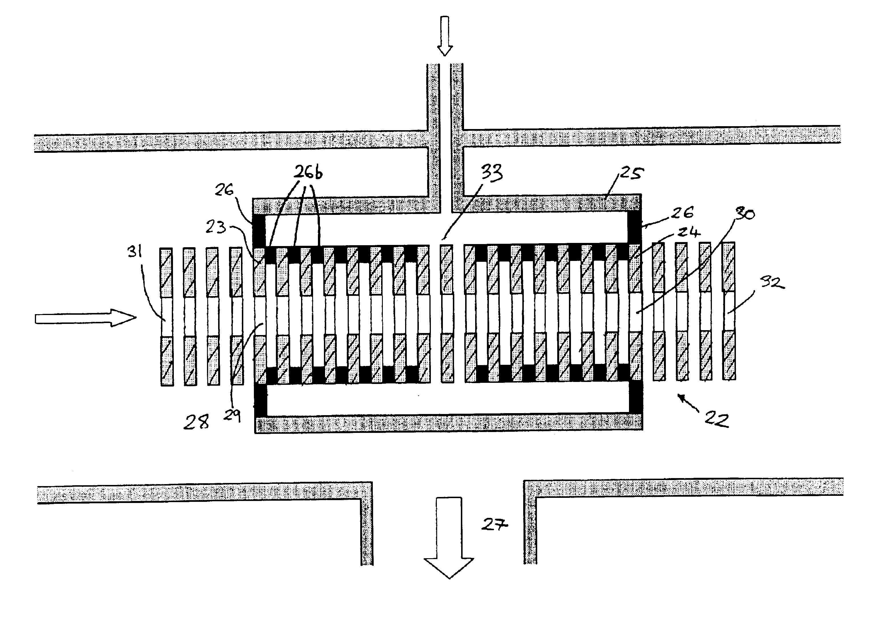
[0021]Conventional ion guide arrangements typically comprise two discrete multipole ion guides with a discrete differential pumping aperture therebetween. Such an arrangement suffers from a disruption to the RF field near the end of a multipole rod set and other end effects. However, according to the preferred embodiment the ions do not leave the ion guide as they pass from one pressure region to another. Accordingly, end effect problems inherent with the conventional arrangements are effectively eliminated thereby resulting in improved ion transmission. The gas collision cell according to the preferred embodiment therefore represents a significant improvement compared to conventional collision cells.
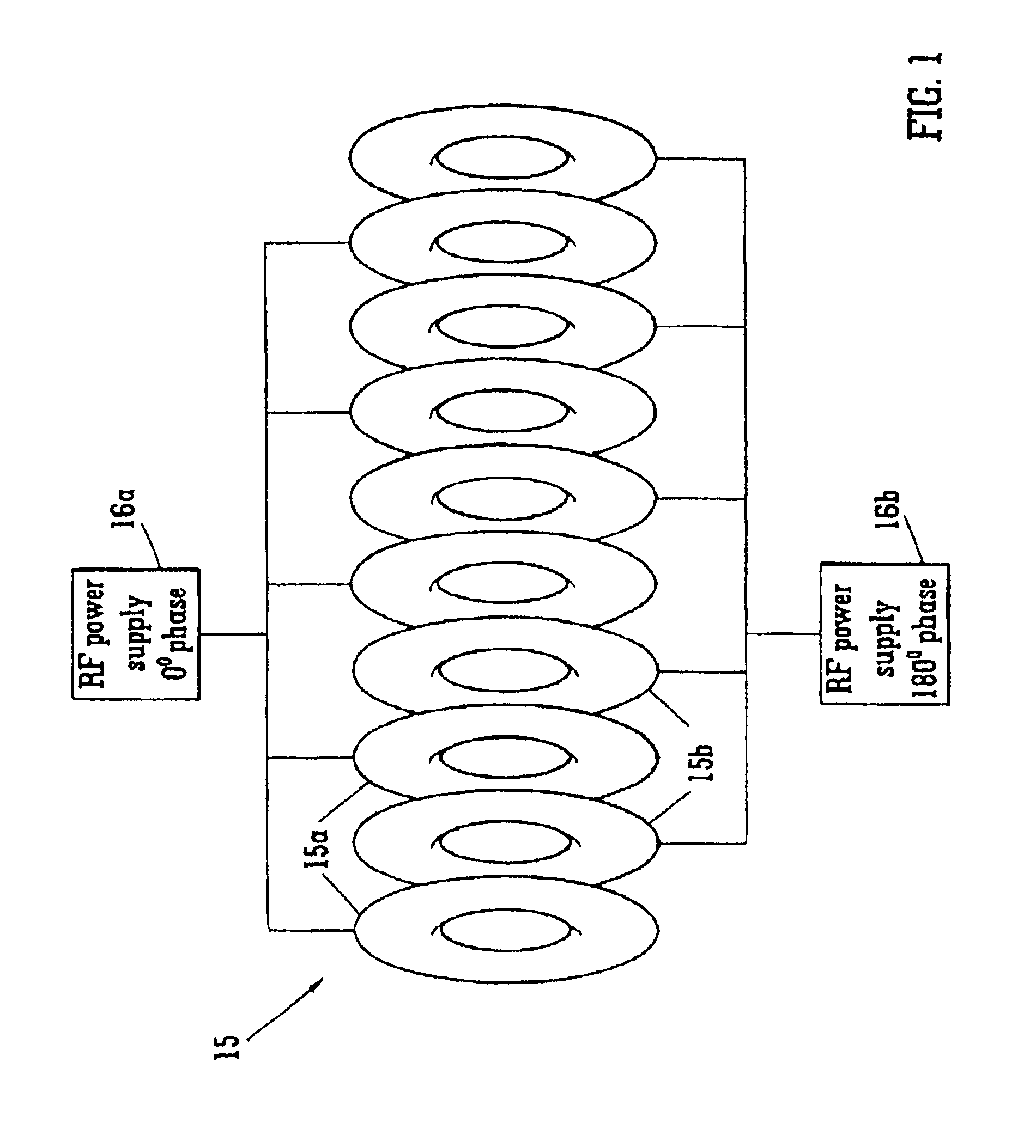
[0057]It has been found that an ion tunnel ion guide exhibits an approximately 25-75% improvement in ion transmission efficiency compared with a conventional multipole, e.g. hexapole, ion guide of comparable length. The reasons for this enhanced ion transmission efficiency are not fully understood, but it is thought that an ion tunnel ion guide may have a greater acceptance angle and a greater acceptance area than a comparable multipole rod set ion guide. Accordingly, one advantage of the preferred embodiment is an improvement in ion transmission efficiency.
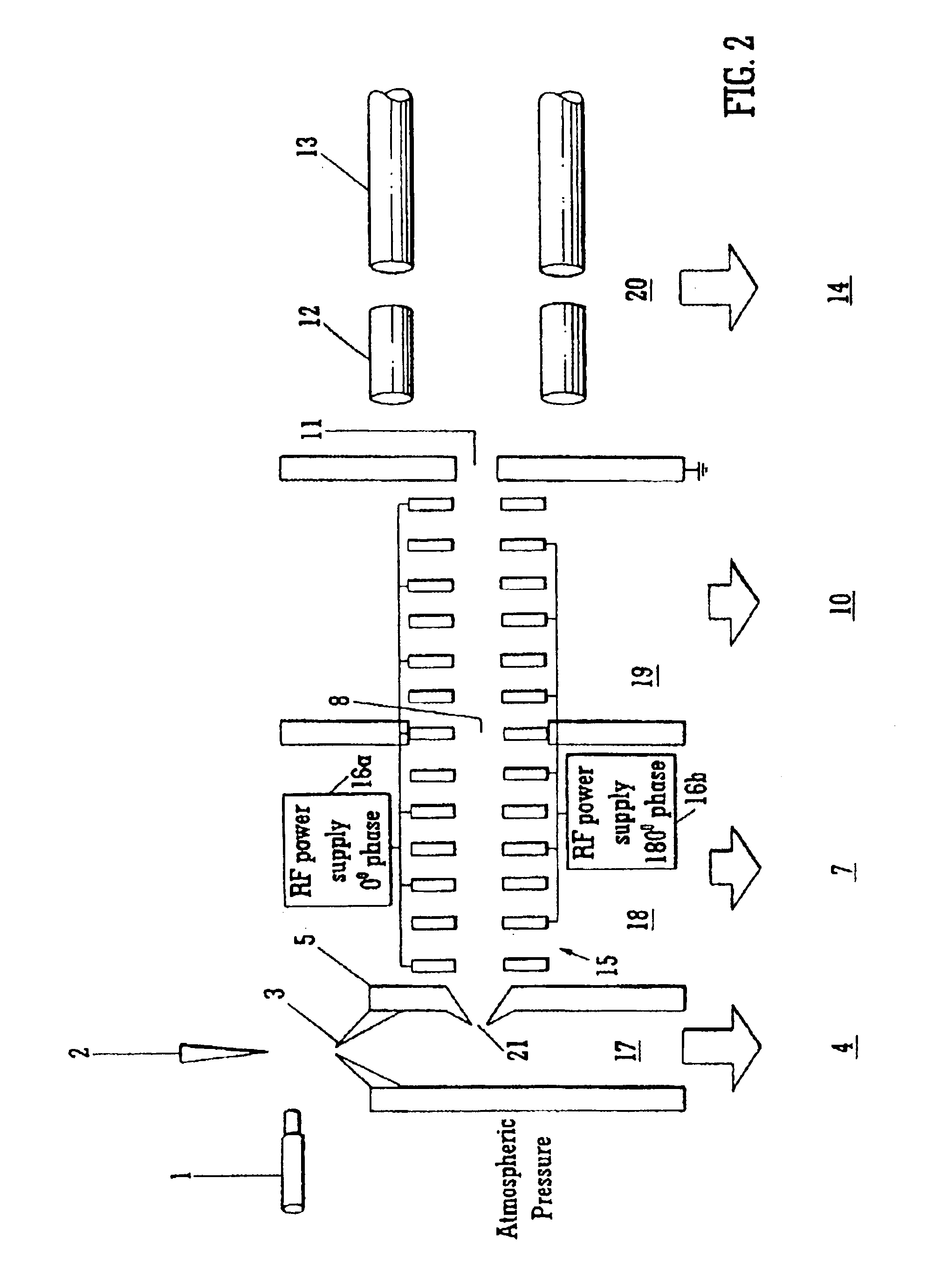
[0060]According to a particularly preferred feature of the present invention, one of the electrodes forming the ion guide forms or constitutes a differential pumping aperture between two pressure regions. Such an arrangement is particularly advantageous since it allows the orifice to be much smaller than that which would be otherwise provided if a multipole rod set ion guide were used. A smaller orifice allows the vacuum pump pumping the vacuum chamber to operate more efficiently.

Problems solved by technology

Such an arrangement suffers from a disruption to the RF field near the end of a multipole rod set and other end effects.

Method used


Image

  • Mass spectrometer
  • Mass spectrometer
  • Mass spectrometer

Examples


Embodiment Construction

[0079]As shown in FIG. 1, an ion tunnel ion guide 15 comprises a plurality of electrodes 15a,15b having apertures. Adjacent electrodes 15a,15b are connected to different phases of an AC or RF power supply. For example, the first, third, fifth etc. electrodes 15a may be connected to the 0° phase supply 16a, and the second, fourth, sixth etc. electrodes 15b may be connected to the 180° phase supply 16b. Ions from an ion source pass through the ion tunnel 15 and are efficiently transmitted by it. In contrast to an ion funnel arrangement, preferably all of the electrodes 15a,15b are maintained at substantially the same DC reference potential about which an AC voltage is superimposed. Unlike ion traps, blocking DC potentials are preferably not applied to either the entrance or exit of the ion tunnel 15.

[0080]FIG. 2 shows an arrangement wherein an Electrospray (“ES”) ion source 1 or an Atmospheric Pressure Chemical Ionisation (“APCI”) ion source 1 (which requires a corona pin 2) emits ion...


PUM


Abstract

A mass spectrometer is disclosed having a gas collision cell. An AC or RF ion guide comprising a plurality of ring electrodes which preferably have the same internal diameter is provided within the gas collision cell. The ion guide extends upstream and / or downstream of the gas collision cell so that ions may be continuously radially confined as they pass from a vacuum chamber maintained at a relatively low pressure, through an inlet differential pumping aperture to the gas collision cell, through the gas collision cell and then out of the gas collision cell through an outlet differential pumping aperture.

Description

BACKGROUND OF THE INVENTION[0001]I. Field of the Invention[0002]The present invention relates to a mass spectrometer and a method of mass spectrometry.[0003]II. Discussion of the Prior Art[0004]Ion guides comprising RF only multipole rod sets such as quadrupoles, hexapoles and octopoles are well known.[0005]Whitehouse and co-workers have disclosed in WO98 / 06481 and WO99 / 62101 an arrangement wherein a multipole rod set ion guide extends between two vacuum chambers. However, as will be appreciated by those skilled in the art, since each rod in a multipole rod set has a typical diameter of around 5 mm, and a space must be provided between opposed rods in order for there to be an ion guiding region, then the interchamber aperture when using such an arrangement is correspondingly very large (i.e. >15 mm in diameter) with a corresponding cross sectional area >150 mm2. Such large interchamber apertures drastically reduce the effectiveness of the vacuum pumps which are most effective ...

Claims


Application Information

Patent Timeline
Patent Type & Authority Patents(United States)
IPC IPC(8): B01D59/44H01J49/00H01J49/06H01J49/26H01J49/36H01J49/42
CPCH01J49/005H01J49/065
Inventor BATEMAN, ROBERT HAROLDGILES, KEVIN
Owner MICROMASS UK LTD
Learn More