[0008]Therefore, an object of the present invention is to provide a piezoelectric speaker improved in acoustic features by weight reduction of a diaphragm of the piezoelectric speaker without decreasing stiffness of the diaphragm or a coefficient of
thermal expansion of surfaces of the piezoelectric speaker.
[0011]According to the above structure, it is possible to achieve reduction in weight of the diaphragm by combining light-weight materials, compared with a diaphragm made of single material. Also, with the sandwich structure of different materials, the diaphragm having required stiffness can be easily designed. Therefore, the diaphragm can achieve required stiffness and light weight simultaneously. With such a light-weight diaphragm, the
sound pressure level of the piezoelectric speaker can be improved.
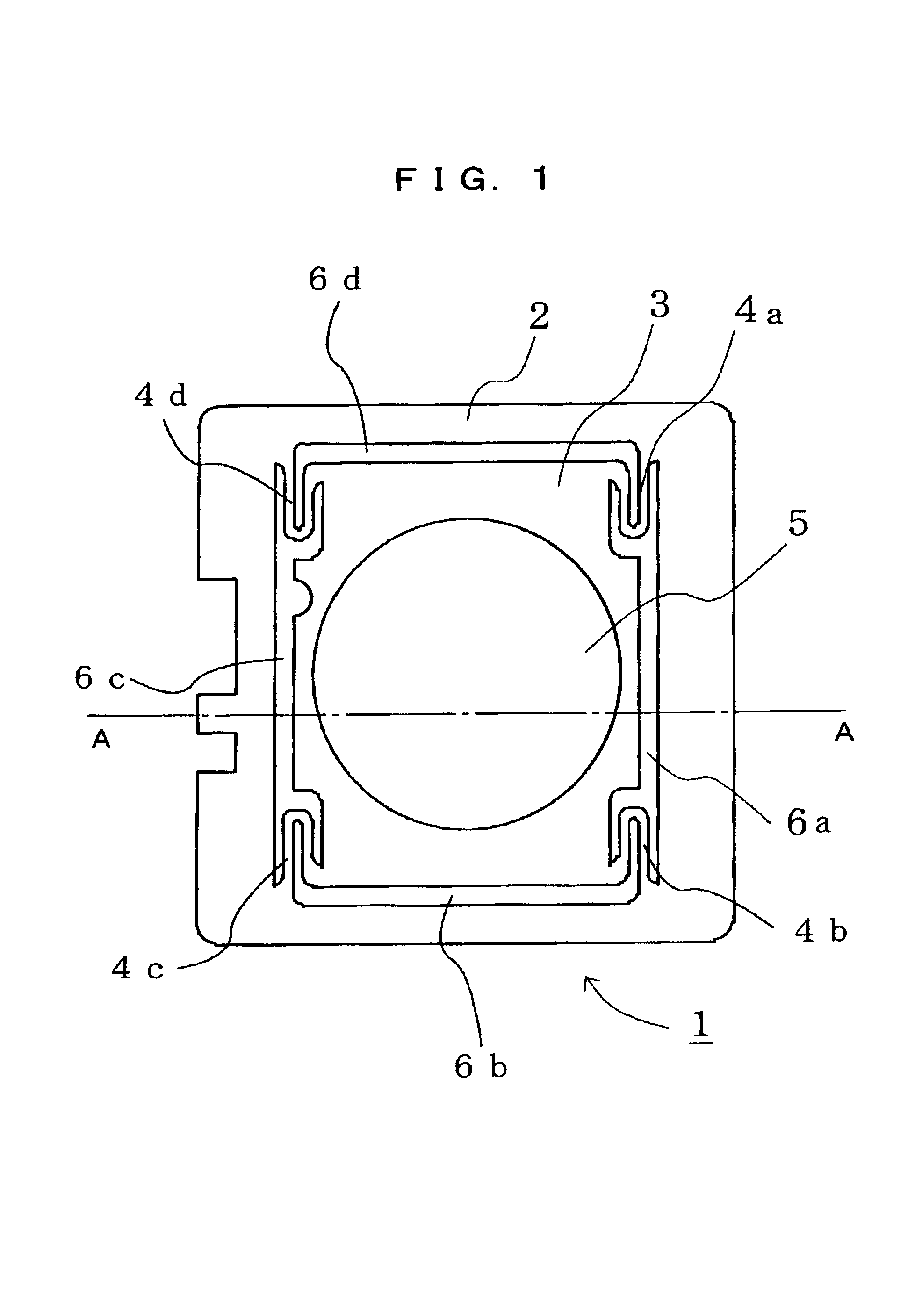
[0012]The clad material may include two surface
layers made of a first material to form both surfaces of the diaphragm; and a
single core layer made of a second material that is different from the first material, and bonded between the two surface
layers. With three-layer clad material made of two different materials, the diaphragm having the required stiffness can be easily designed and manufactured.
[0013]A coefficient of thermal expansion of the first material may be close to a coefficient of thermal expansion of the piezoelectric element. The density of the second material may be lower than a density of the first material. With this, it is possible to achieve a light-weight diaphragm having a coefficient of thermal expansion of the surface material of the diaphragm close to that of the piezoelectric element. Therefore, thermal exfoliation of the surface material from the piezoelectric element and thermal material destruction such as
cracking can be avoided. That is, with the material having the core layer lighter in weight than that of the surface
layers, it is possible to achieve a light-weight diaphragm having a coefficient of thermal expansion close to that of the piezoelectric element. Also, the
surface layer may be thinner than the core layer. In this case, since the light-weight core layer forms a large proportion of the diaphragm, it is possible to achieve effects of further reducing the weight of the diaphragm.
[0014]The first and second materials may be ones selected out of a
metal film and a film made of
high polymer resin. This provides improved flexibility in selecting the materials for constructing the diaphragm. Furthermore, the first material may be the
metal film made of 42
alloy stainless, and the second material may be one selected out of the metal film made of metal other than the 42 alloy stainless, and the film made of
high polymer resin. Therefore, when the piezoelectric element is made of
lead zirconate titanate (PZT) as generally used, the coefficient of thermal expansion of the surface layers becomes close to that of the piezoelectric element. With this construction, thermal exfoliation of the surface material from the piezoelectric element and thermal material destruction such as
cracking can be avoided. Also, with the material of the core layer lighter in weight than 42 alloy stainless, it is possible to achieve a light-weight diaphragm having the coefficient of thermal expansion close to that of the PZT piezoelectric element. Still further, the second material may be a film made of
aluminium. With the surface layers made of 42 alloy stainless and the core layer made of
aluminium, it is possible to easily achieve the above-mentioned diaphragm.
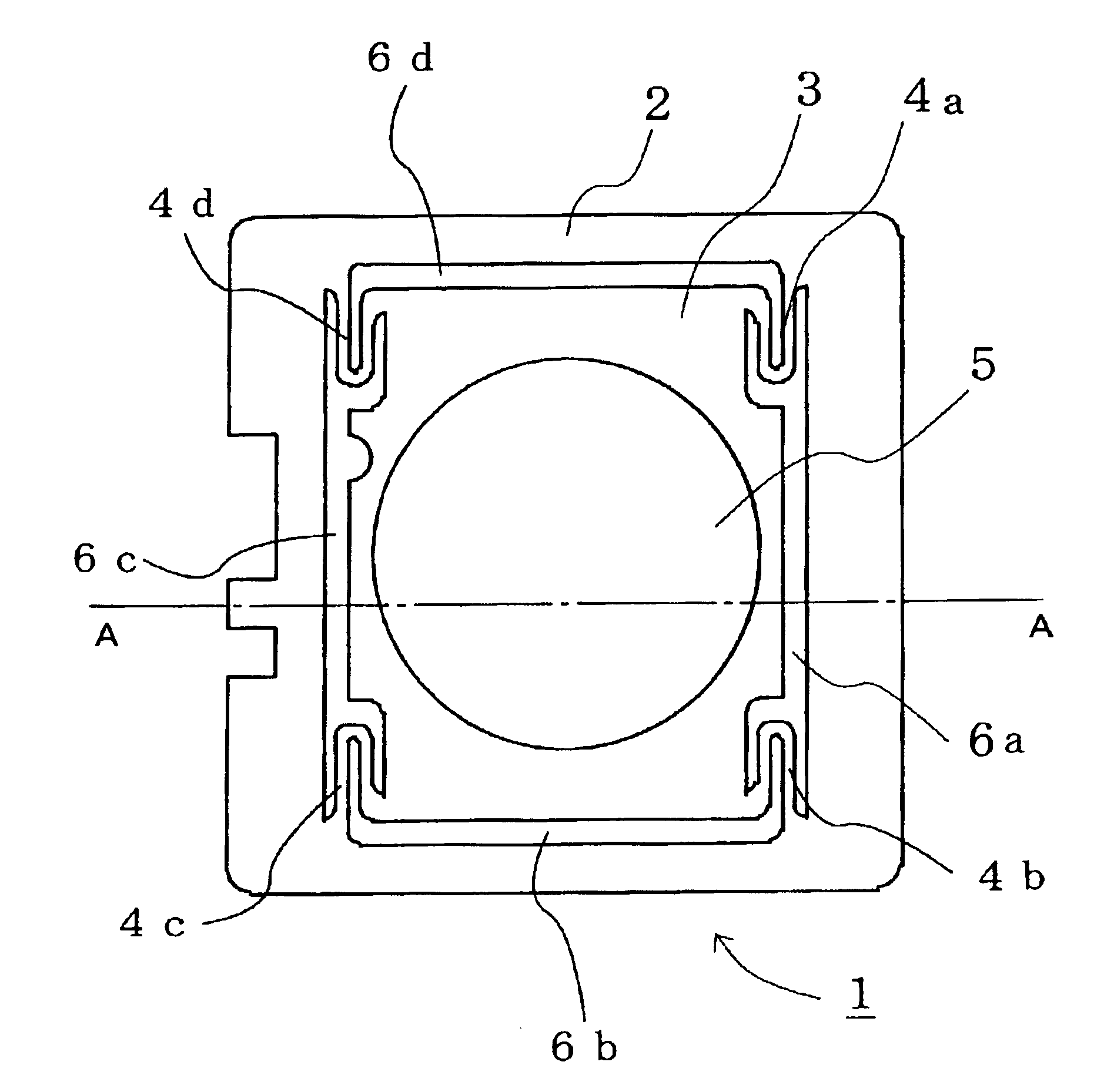
[0015]Still further, the piezoelectric speaker may further include a frame portion surrounding the diaphragm; a
damper portion connecting the frame portion and the diaphragm, and supporting the diaphragm so that the diaphragm can linearly vibrate; and an edge portion formed in an area delineated by the diaphragm, the
damper portion, and the frame portion. The clad material having the layers made of the first and second materials laminated together may be subjected to a predetermined process to integrally form the diaphragm, the
damper portion, and the frame portion. With the diaphragm, the damper portion, and frame portion integrally formed of the clad material, a speaker portion of the piezoelectric speaker can be easily formed. Still further, the edge portion may be formed by, for example, filling a material that is different from the first and second materials in a space formed among the diaphragm, the damper portion, and the frame portion. In this case, the edge portion for flattening frequency characteristics of the piezoelectric speaker can be appropriately formed. In another example, the edge portion may be formed by performing an
etching process onto only the first material in the area delineated among the diaphragm, the damper portion, and the frame portion. In this case, the edge portion for flattening frequency characteristics of the piezoelectric speaker can be easily formed only by the
etching process. Still further the frame portion may be provided with one
electrode for applying a driving
voltage to the piezoelectric element. In this case, when the frame portion is taken as one of electrodes,
electricity is conducted to the diaphragm through the damper portion. Therefore, the piezoelectric element can be driven without taking the diaphragm as one of the electrodes. This can dispense with wiring directly to the diaphragm, thereby stabilizing vibration characteristics of the diaphragm.

