Hydraulic control system

a control system and hydraulic technology, applied in mechanical control devices, fluid couplings, servomotors, etc., can solve the problems of deteriorating energy efficiency, difficult to appropriately adjust areas and timing, useless energy cast away, etc., and achieve the effect of suppressing energy loss

Inactive Publication Date: 2005-12-27
NABLESCO CORP
View PDF4 Cites 12 Cited by
  • Summary
  • Abstract
  • Description
  • Claims
  • Application Information

AI Technical Summary

Benefits of technology

[0023]Accordingly, the object of the present invention is to provide a hydraulic control system having preferred operating performance, response and stability, and drastically enhancing the system efficiency.
[0055]Also, in the case, spring force for setting differential pressure in the flow control valve with pressure compensation can be reduced when a specific actuator is operated.
[0063]This minimum discharge rate can be very small depending on a mechanism of the pressure generating means and the discharge rate control means. So, energy loss can be suppressed at minimum level.

Problems solved by technology

Particularly in case that a hydraulic actuator connected to the valve is in the type of heavy load, that is, requires large volume of pressure oil to actually start to move and therefore the operation quantity of the directional control valve is large, there is still a problem that the pressure oil is cast away during the time interval and as the result energy is cast away uselessly, though the discharge rate of the pump is held to be small by the pressure oil.
However, it is very difficult to appropriately adjust areas and timing between the opening of the center bypass passage and the aperture passage to the cylinder port in the directional control valve.
Furthermore, depending on machining accuracy and valve operation, pressure oil discharged from the pump is trapped in a passage of supply lines to cause abnormally high pressure generation that rather deteriorates energy efficiency.
Accordingly, there is still a problem that preferred operating performance may not be maintained when revolution numbers of an engine or load pressure change.
In the Posi-con system, there is a similar problem as in the Nega-con system, in view of system efficiency and operating performance in combined operations in spite of the preferred operating performance, because a part of the pressure oil is discharged through the center bypass passage to a tank while the valve is in neutral position or on the way of operation.
Therefore it is very difficult to adjust areas and timing between the opening of the center bypass passage and the aperture passage to the cylinder port, so there is still a problem that abnormally high pressure generation and delay of rising in pressure may cause in the passage of supply lines from the pump.
Thus, there is still a problem in view of system efficiency.
Furthermore, as to the control of the pump discharge rate, there is another problem of delay in response, because first, the directional control valve is operated, and then, as the result, the pump discharge rate is controlled.

Method used


Image

  • Hydraulic control system
  • Hydraulic control system
  • Hydraulic control system

Examples


Embodiment Construction

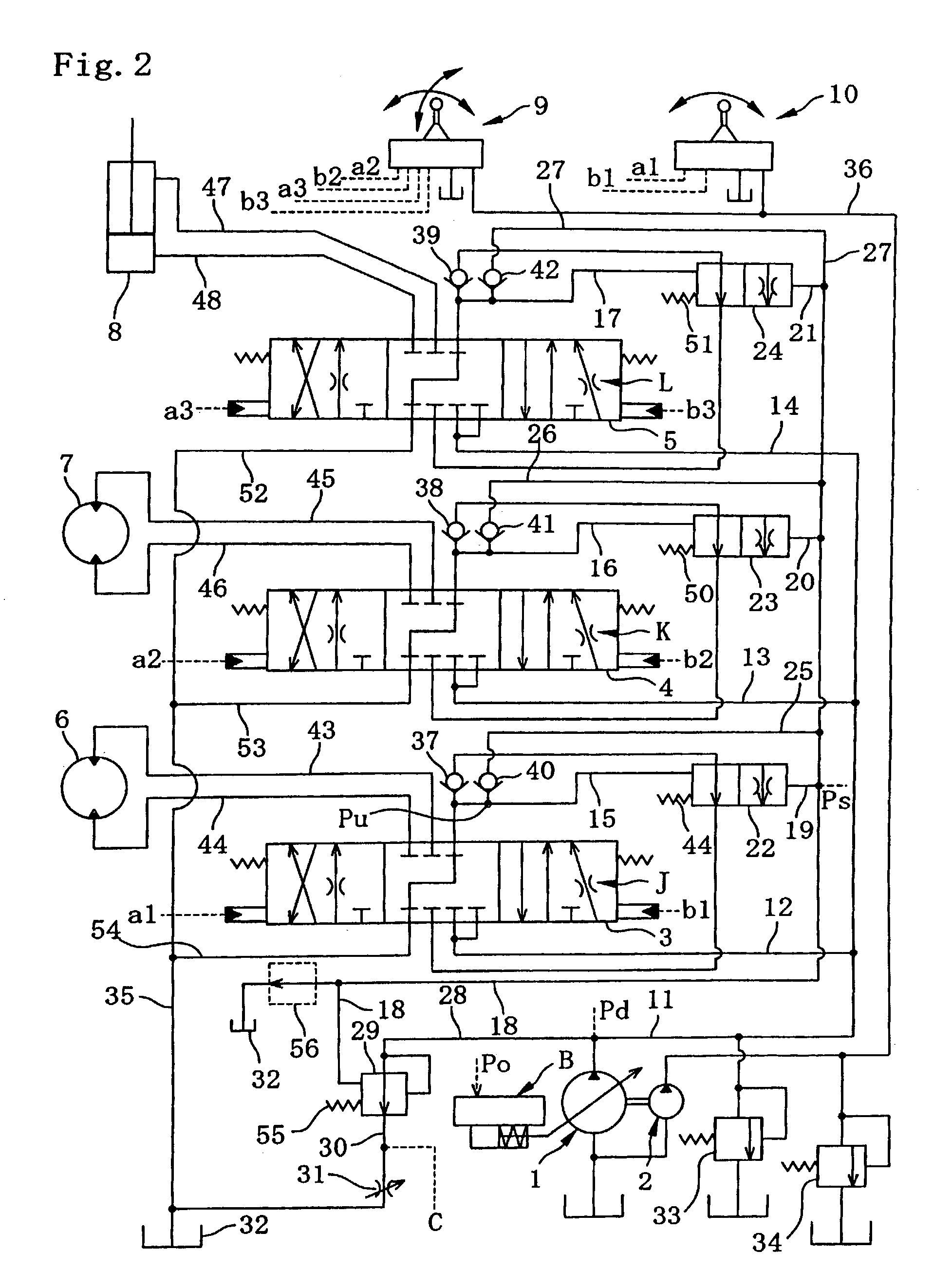
[0082]Referring to FIG. 1 to FIG. 13, preferred embodiment of the present invention will be explained below.

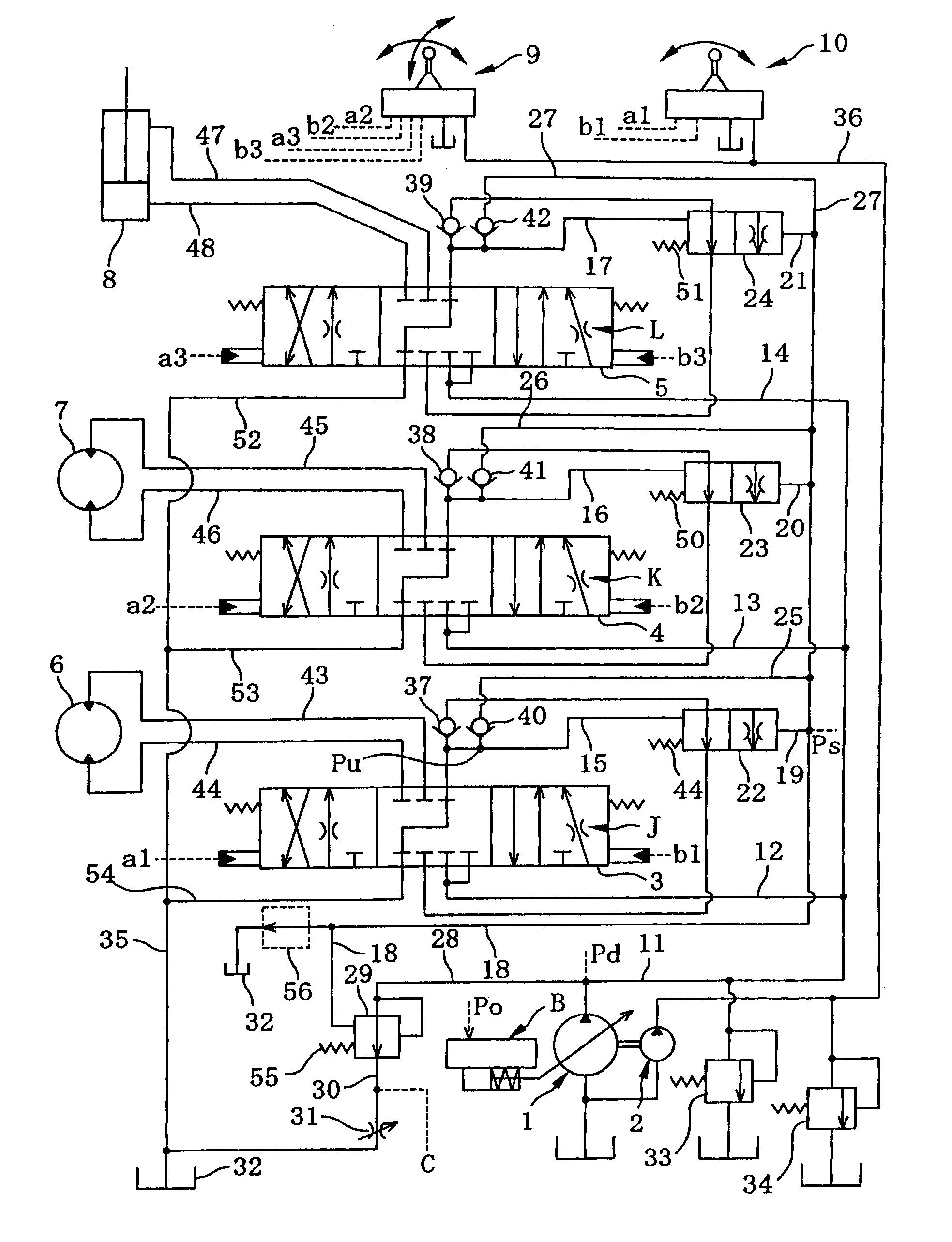
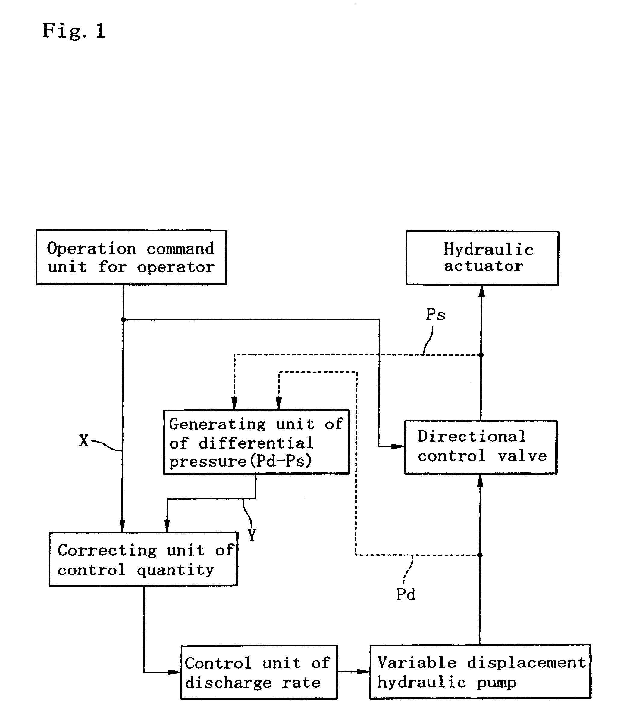
[0083]FIG. 1 shows a conceptual control block diagram of the present invention. In FIG. 1, discharge rate of the variable displacement hydraulic pump is controlled by the control unit of discharge rate. The pressure oil discharged from the variable displacement hydraulic pump is supplied to one or a plurality of hydraulic actuators through the directional control valve unit including one or a plurality of directional control valves and the peripheral hydraulic circuits thereof.

[0084]The operation command unit instructs direction and quantity for operating each hydraulic actuator as a pilot operated pressure oil signal to each directional control valve. Further, the operation command unit instructs a discharge rate control signal X as a pressure oil signal to the correcting unit of control quantity. This pressure oil signal X is selected as the highest pressure oil signal among...


PUM


Abstract

A hydraulic control system is presented that includes a hydraulic actuator, an operation command unit that provides a first control operation signal, a directional control valve unit with a directional control valve that supplies pressure oil to the hydraulic actuator based on the first control operation signal, a variable displacement hydraulic pump having a discharge rate that changes in response to the first control operation signal, a differential pressure generating unit that generates a differential pressure between pressure of the hydraulic pump and oil pressure and outputs a second control operation signal indicative of the differential pressure. The hydraulic control system further includes a control quantity correcting unit that corrects the first control operation signal based on the second control operation signal, and a discharge rate control unit that controls the discharge rate of the variable displacement hydraulic pump based on the corrected first control operation signal.

Description

BACKGROUND OF THE INVENTION[0001]1. Field of the Invention[0002]The present invention relates to a hydraulic control of a construction machinery operated by hydraulic transmission such as a hydraulic shovel, specifically to a hydraulic control system drastically enhancing the system efficiency improving operating performance thereof.[0003]2. Description of Related Art[0004]There are a negative feedback control system (hereinafter called as “Nega-con system”), a positive feedback control system (hereinafter called as “Posi-con system”), and a load sensing system, etc. as the hydraulic control system of the hydraulic shovel.[0005]The matters in question of the above each conventional system are explained below.[0006]Nega-con System:[0007]FIG. 14 illustrates a hydraulic circuit diagram of the Nega-con system.[0008]In the system, there is provided with a pressure generating means at an outlet of a center bypass passage in a directional control valve with a center bypass passage. The pre...

Claims


Application Information

Patent Timeline
Patent Type & Authority Patents(United States)
IPC IPC(8): E02F9/22F15B11/00F16D31/02G05G9/047
CPCE02F9/2235E02F9/2285E02F9/2296F16D31/02G05G2009/04766F15B11/00F15B11/17
Inventor MATSUMOTO, SATOSHISHINKE, TAKASHIKOBAYASHI, MASAYUKI
Owner NABLESCO CORP
Why Eureka
Try Eureka