Plate supplying apparatus

a technology for supplying apparatuses and plates, applied in the directions of pile separation, transportation and packaging, article separation, etc., can solve the problems of low reliability of peeling off slip sheets s, and easy damage to image recording layers of plates. to prevent damage to image recording layers of plates

Inactive Publication Date: 2005-12-27
DAINIPPON SCREEN MTG CO LTD
View PDF7 Cites 19 Cited by
  • Summary
  • Abstract
  • Description
  • Claims
  • Application Information

AI Technical Summary

Benefits of technology

[0019]Therefore, an object of the present invention is to provide a plate supplying apparatus capable of preventing an image recording layer of a plate from being damaged when shaking a slip sheet off the plate.
[0020]Another object of the present invention is to provide a plate supplying apparatus capable of reducing a moment of force applied to an arm when transferring a plate, thereby reducing the cost of a motor for driving the arm.
[0021]Still another object of the present invention is to provide a plate supplying apparatus capable of supplying a plate of any thickness without increasing the size of the apparatus itself by reducing a repulsive force generated in the plate being transferred such that its faces are reversed, thereby preventing a drop of the plate during transfer.

Problems solved by technology

Since the image recording layer is easily damaged, the utmost caution is required when supplying the plate.
However, in such a conventional plate supplying apparatus 200 which is configured to peel off the slip sheet S adhering to the back face of the plate P by causing the plate P to stand still for a prescribed time period during transfer, the reliability of peeling off the slip sheet S is low.
As described above, in the section from the angle a to the angle b, vibration is applied to the plate P. Accordingly, the pushing force due to the bending stress and the vibration are simultaneously applied to the plate P, and therefore, in some cases, friction is caused between pushed portions of the plate P, resulting in damage to an image recording layer of the plate P.
Therefore, a drive force of the motor 208 for driving the traveling member 204 is required to be increased, resulting in a cost increase.
In such a case, for example, the arm 202 is required to be lengthened, resulting in upsizing of the plate transfer mechanism.
Moreover, the drive force of the motor 208 is required to be increased, leading to the upsizing and cost increase of the plate supplying apparatus 200.
Thus, a mechanism for detecting the thickness of the plate P and a mechanism for controlling the negative pressure are required, leading to a cost increase of the plate supplying apparatus 200.

Method used


Image

  • Plate supplying apparatus
  • Plate supplying apparatus
  • Plate supplying apparatus

Examples


first embodiment

[0069](First Embodiment)

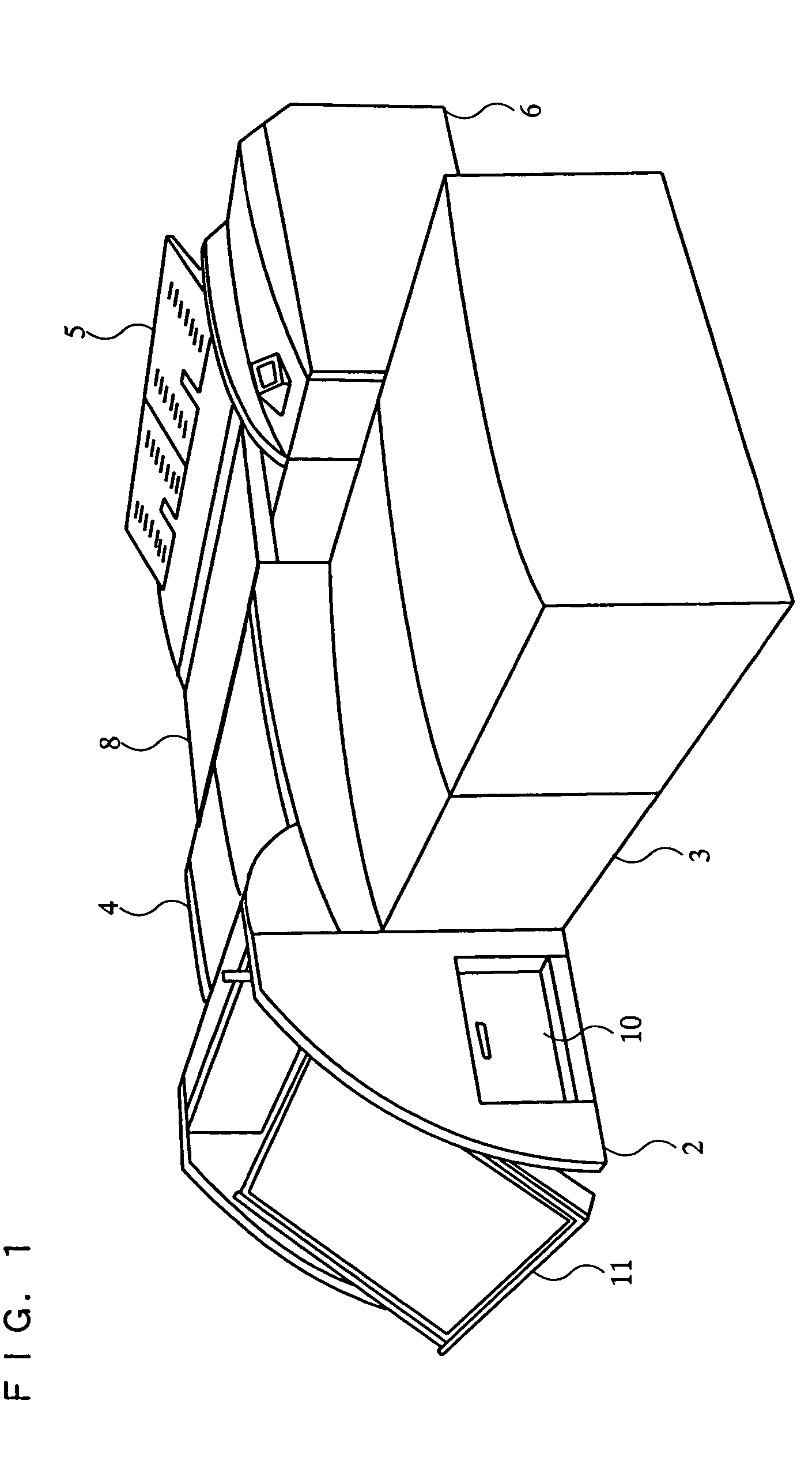
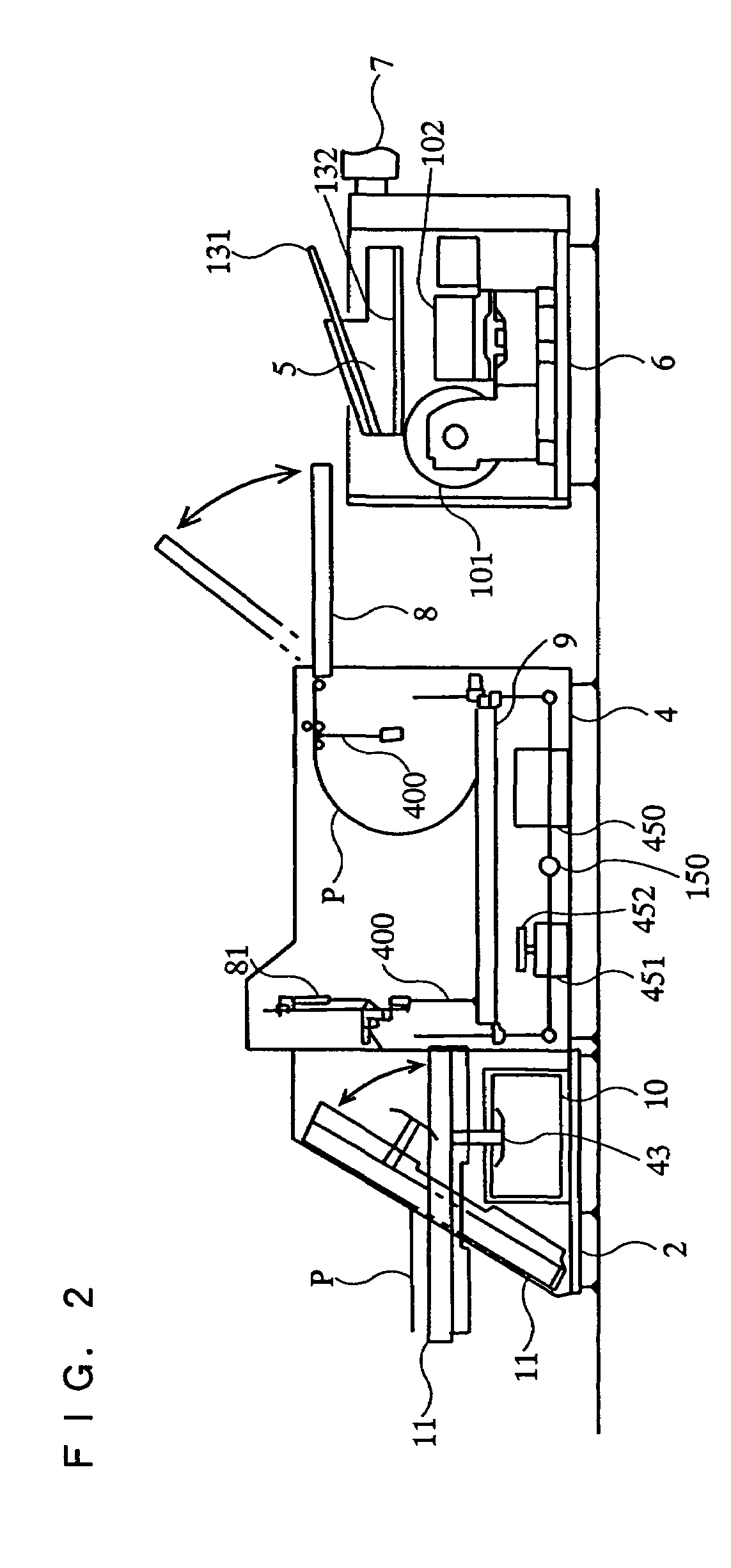
[0070]A plate supplying apparatus according to a first embodiment of the present invention will be described below. FIG. 1 is a perspective view of an image recording system including the plate supplying apparatus according to the first embodiment. FIG. 2 is a schematic side view of the image recording system illustrated in FIG. 1.

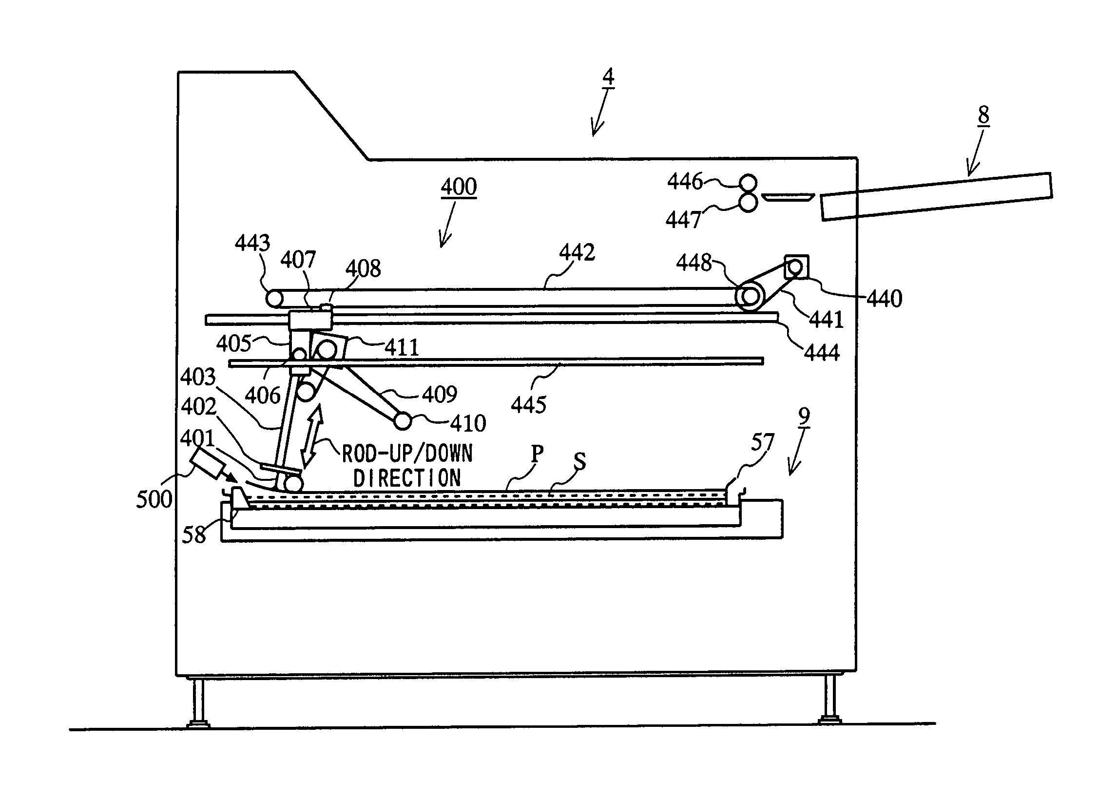
[0071]In FIGS. 1 and 2, the image recording system includes: a plate supplying section 2 used for storing plates P into each of a plurality of cassettes 9; a multicassette section 3 accommodating the plurality of cassettes 9 stacked together in a vertical direction; a plate supplying apparatus 4 (hereinafter, referred to as the “autoloader section 4”) for taking a plate P out from a cassette 9 having moved to a plate supply position and transferring that plate P; a feed and ejection tray section 5 having a plate feed tray 131 and a plate ejection tray 132; a conveyer section 8; an image recording section 6 for recording an image ont...

second embodiment

[0112](Second Embodiment)

[0113]A plate supplying apparatus according to a second embodiment of the present invention will be described below. An image recording system including the plate supplying apparatus according to the second embodiment has a structure similar to that of the image recording system including the plate supplying apparatus according to the first embodiment. In the following description, elements similar to those of the image recording system according to the first embodiment are denoted by the same reference numerals. Detailed description of such elements is omitted herein.

[0114]Referring to FIGS. 14 to 18, described below are a structure of a slide mechanism for moving a cassette 9 between a multicassette section 3 and an auto loader section 4, and a structure of a raising and lowering mechanism 150 for raising and lowering the cassette 9 within the autoloader section 4. FIG. 14 is a schematic top view of the image recording system including the plate supplying ...


PUM

PropertyMeasurementUnit
thicknessaaaaaaaaaa
thicknessaaaaaaaaaa
angleaaaaaaaaaa

Abstract

In the plate supplying apparatus of the present invention, various vibrations are provided to a plate secured via suction during a separating operation by causing pad rods 403 to repeat a slight ascent and a pause, and thereafter causing the pad rods 403 to make an abrupt descent, thereby reliably peeling off a slip sheet adhering to the back face of the plate. Further, vibration in the rod-up / down direction is provided to the plate during the separating operation, and the plate is not pushed hard. Thus, it is possible to prevent the plate from being damaged. A raising and lowering motor 52 is driven to lower the cassette 9. A separating operation for peeling off a slip sheet S adhering to the back face of the plate P is performed, and thereafter the plate P secured via suction is turned over and transferred.

Description

[0001]The present application is a divisional of U.S. application Ser. No. 10 / 674,511 filed on Oct. 1, 2003, now issued as U.S. Pat. No. 6,776,097.BACKGROUND OF THE INVENTION[0002]1. Field of the Invention[0003]The present invention relates to a plate supplying apparatus, and more particularly to a plate supplying apparatus for supplying a plate, which is transferred such that its faces are reversed, from a storage section in which a plurality of plates are piled such that each plate alternates with a slip sheet.[0004]2. Related Art Statement[0005]A conventional plate supplying apparatus automatically supplies a plate, such as a presensitized (PS) plate, to an image recording apparatus for irradiating that plate with a laser beam to directly record an image thereon. The plate used with such an image recording apparatus includes a support layer and an image recording layer. Since the image recording layer is easily damaged, the utmost caution is required when supplying the plate. In ...

Claims


Application Information

Patent Timeline
Patent Type & Authority Patents(United States)
IPC IPC(8): B41F1/00B41L47/14B65H3/08
CPCB65H1/14B65H3/0816B65H3/0825B65H2301/33214B65H2513/51B65H2701/18264B65H2701/1928B65H2801/21B65H2220/02
Inventor TAKEDA, MORIHIRO
Owner DAINIPPON SCREEN MTG CO LTD
Why Eureka
Try Eureka