Piezoelectric fuel injection system with rate shape control and method of controlling same

a fuel injection system and rate shape technology, applied in the direction of electric control, fuel injecting pumps, machines/engines, etc., can solve the problems of increasing the control volume pressure and closing of the needle valve, the reference does not provide a solution for effectively controlling the rate shape of the fuel injection, and the desired effect of fuel economy

Inactive Publication Date: 2005-12-27
CUMMINS INC
View PDF21 Cites 30 Cited by
  • Summary
  • Abstract
  • Description
  • Claims
  • Application Information

AI Technical Summary

Benefits of technology

[0013]In view of the foregoing, an aspect of the present invention is a piezoelectric fuel injection system to aid in reducing exhaust emissions and improving fuel economy, especially in engines not using exhaust gas recirculation.
[0014]Another aspect of the present invention is a piezoelectric fuel injection system having enhanced rate shape control.
[0015]Still another aspect of the present invention is a method for controlling a piezoelectric fuel injection system in which enhanced rate shape is attained.

Problems solved by technology

Opening of the injection control valve causes a reduction in the fuel pressure in the control volume resulting in a pressure differential which forces the needle valve open, and closing of the injection control valve causes an increase in the control volume pressure and closing of the needle valve.
Although the above-described reference provides some control over fuel metering, and thus, control over the amount of fuel injected, the reference does not provide a solution for effectively controlling rate shape of the fuel injections.
However, controlling the rate shape of fuel injections by varying the input signal in the manner known has been found to not provide the desired results in various instances when accurate rate shaping would be desirable.
Therefore, there still exists an unfulfilled need for a piezoelectric fuel injection system having enhanced rate shape control, and a method for controlling a piezoelectric fuel injector in which enhanced rate shape is attained.

Method used


Image

  • Piezoelectric fuel injection system with rate shape control and method of controlling same
  • Piezoelectric fuel injection system with rate shape control and method of controlling same
  • Piezoelectric fuel injection system with rate shape control and method of controlling same

Examples


Embodiment Construction

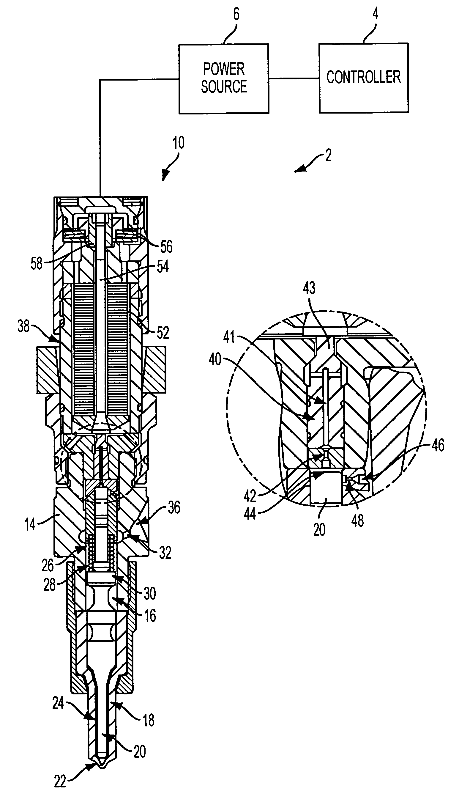
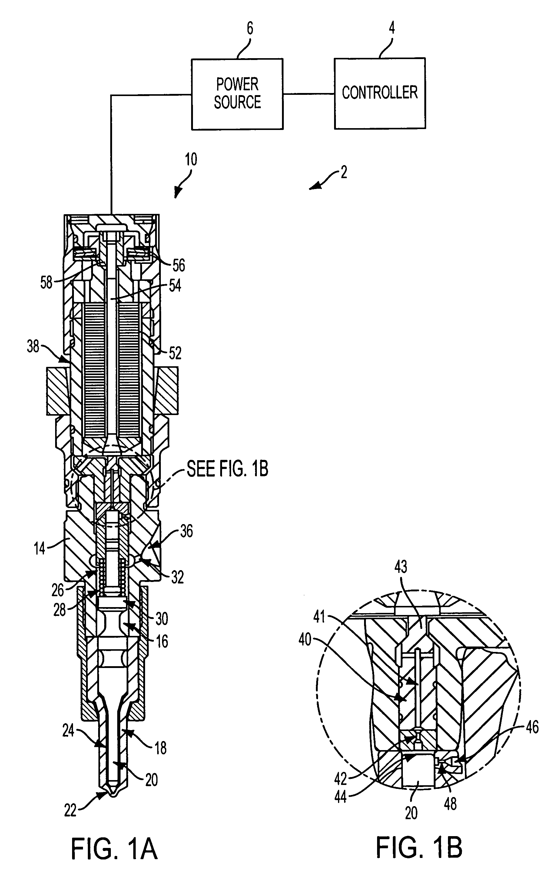
[0030]FIG. 1 shows a schematic illustration of a piezoelectric fuel injection system 2 in accordance with one embodiment of the present invention that avoids the above noted limitations of conventional fuel injection systems. As described in further detail below, the piezoelectric fuel injection system 2 allows enhanced control of the rate of fuel injected during an injection event of a combustion cycle in an internal combustion engine, for example, a diesel engine, so that the injection rate shape can be effectively controlled. Of course, the present invention may also be applied to other types of internal combustions as well.

[0031]The piezoelectric fuel injection system 2 of the illustrated embodiment includes a controller 4, e.g. electronic control unit, that is connected to a power source 6, the controller 4 being adapted to control the power source 6. The power source 6 of the piezoelectric fuel injection system 2 is connected to a fuel injector 10 and provides power thereto in...


PUM


Abstract

A piezoelectric fuel injection system and a method of controlling same are provided which include a piezoelectric fuel injector having a piezoelectric element, a power source adapted to provide power to the piezoelectric element to actuate the piezoelectric fuel injector, and a controller adapted to charge the piezoelectric element to an initial voltage to begin said injection event, to decrease the voltage from the initial voltage to an intermediate voltage, and to increase the voltage from the intermediate voltage to a primary voltage to thereby control the injection rate shape. The initial voltage level is at least approximately equal to said primary voltage level and preferably approximately equal to a maximum voltage rating. The initial voltage duration, the intermediate voltage duration and the magnitude of the intermediate voltage can be changed or varied to modify the injection or rate shape.

Description

BACKGROUND OF THE INVENTION[0001]1. Field of the Invention[0002]The present invention is directed to piezoelectric injection systems having a mechanism for controlling rate shape, and to methods for controlling such piezoelectric injection systems.[0003]2. Description of Related Art[0004]In most fuel supply systems applicable to internal combustion engines, fuel injectors are used to inject fuel pulses into the engine combustion chamber. A commonly used injector is a closed-nozzle injector which includes a nozzle assembly having a spring-biased nozzle valve element positioned adjacent the nozzle orifice for allowing fuel to be injected into the cylinder. The nozzle valve element also functions to provide a deliberate, abrupt end to fuel injection thereby preventing a secondary injection which causes unburned hydrocarbons in the exhaust. The nozzle valve is positioned in a nozzle cavity and biased by a nozzle spring so that when the pressure of the fuel within the nozzle cavity excee...

Claims


Application Information

Patent Timeline
Patent Type & Authority Patents(United States)
IPC IPC(8): F02D41/20F02M37/04F02M47/02F02M59/46F02M61/16F02M63/00
CPCF02D41/2096F02M45/12F02M47/027F02M61/161F02M63/0026F02M63/004F02M63/0043F02M63/0068
Inventor RAUZNITZ, PETERPETERS, LESTER L.CROFTS, JOHN D.MEYER, WILLIAM D.
Owner CUMMINS INC
Why Eureka
Try Eureka