Low profile anastomosis connector

a low-profile, connector technology, applied in the direction of surgical staples, mechanical equipment, applications, etc., can solve the problems of non-trivial profile of the connector, limited elastic, super-elastic and shape-memory bending mechanisms with respect, and damage to nearby tissu

Inactive Publication Date: 2005-12-27
BY PASS
View PDF273 Cites 68 Cited by
  • Summary
  • Abstract
  • Description
  • Claims
  • Application Information

AI Technical Summary

Benefits of technology

[0006]An aspect of some preferred embodiments of the invention relates to providing a pivot bar on which a spike of an anastomosis device is mounted. In a preferred embodiment of the invention, the pivot bar is not part of the mechanical structure of the connector, allowing the spike to deform independently of the deformation of the rest of the connector, even if the device deformation is not restricted by a mold. In a preferred embodiment of the invention, the pivot bar is used to provide apply sufficient force to the spike, without requiring a significant bending radius. Thus, a device whose profile conforms to the blood vessels being connected, can be provided. Such a pivot bar can be provided for spikes that engage one blood vessel or both blood vessels.

Problems solved by technology

One drawback of some connectors is their non-trivial profile, i.e., the connectors project outside of the volume defined by the anastomosis region.
As many such connectors are formed of hard materials, these extensions may damage nearby tissue.
One cause of these projections has been the use of spikes that are bent during the anastomosis procedure.
It is noted that elastic, super-elastic and shape-memory bending mechanisms are limited with respect to the amount of elongation that the mechanism can faithfully retain.
With plastic deformations, the bending is limited by the danger of mechanical failure.
In general, the range of materials (and their mechanical characteristics) available for implantation is quite limited, due to bio-compatibility considerations.

Method used


Image

  • Low profile anastomosis connector
  • Low profile anastomosis connector
  • Low profile anastomosis connector

Examples


Embodiment Construction

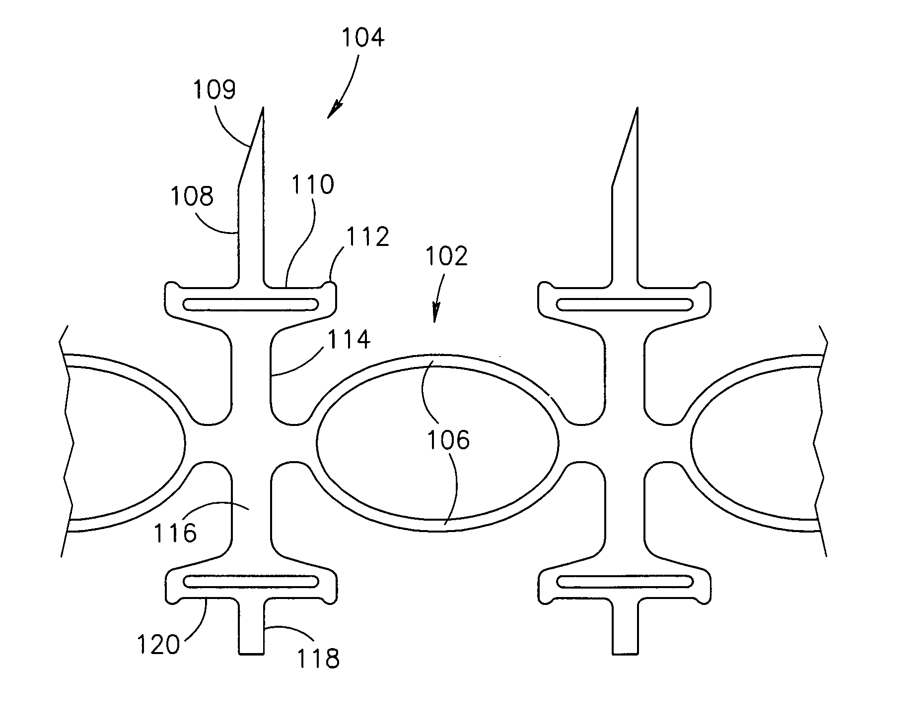
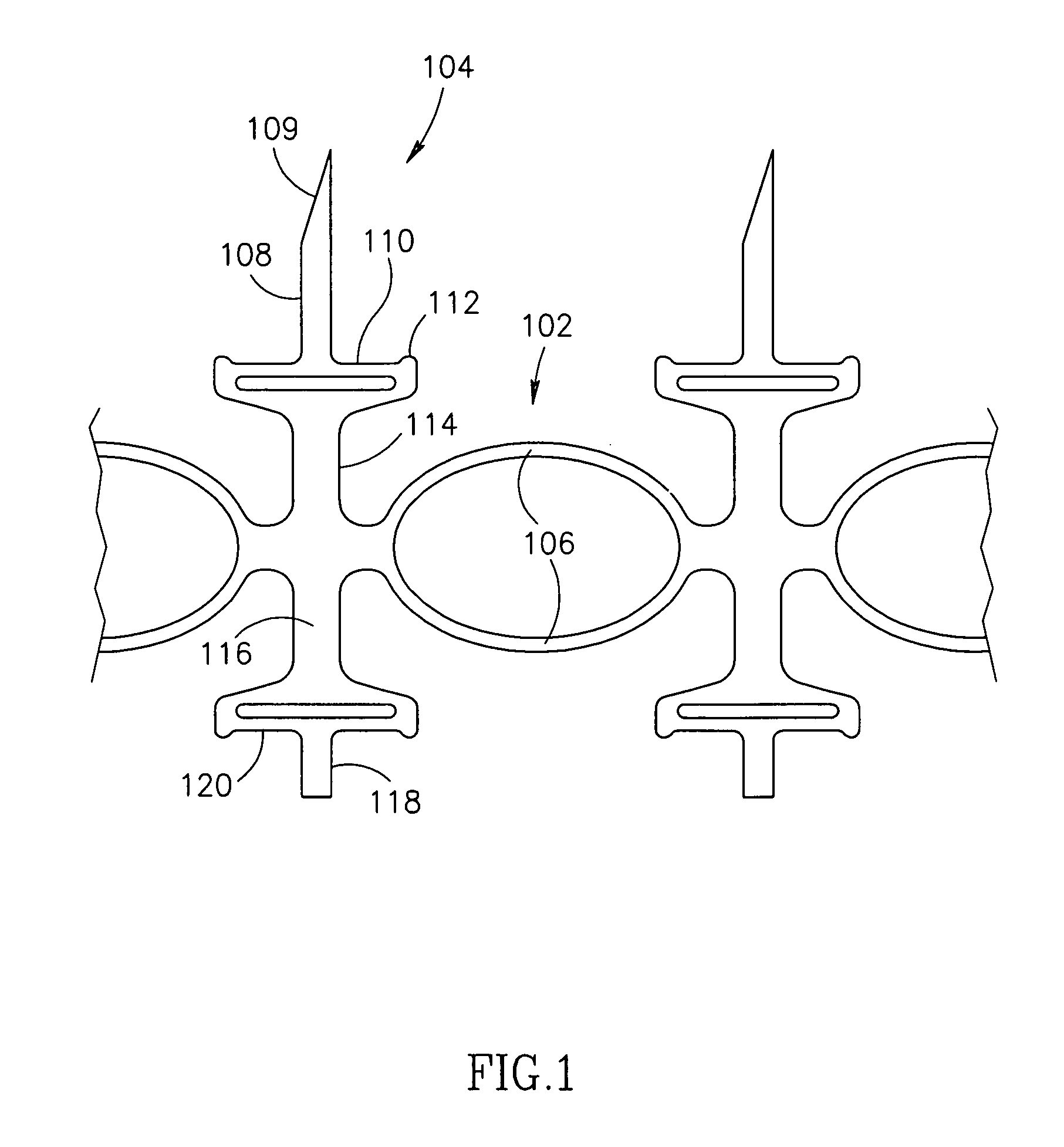
[0093]FIG. 1 is plan view of a part of a pivot-bar based anastomotic connector 100, in accordance with a preferred embodiment of the invention. Connector 100 is generally ring shaped, formed of a plurality of ring segments 102 and a plurality of spike elements 104 interspersed between the ring segments. It is noted however, that other connector designs, can be used, for example, the spike elements being independent of the ring segments.

[0094]A ring segment forms part of the ring structure of the connector and is typically, but not always, radially compressed, to allow easier insertion into a blood vessel. In a preferred embodiment of the invention, each ring segment 106 comprises a plurality of side-by-side elements 106, which are preferably elastic.

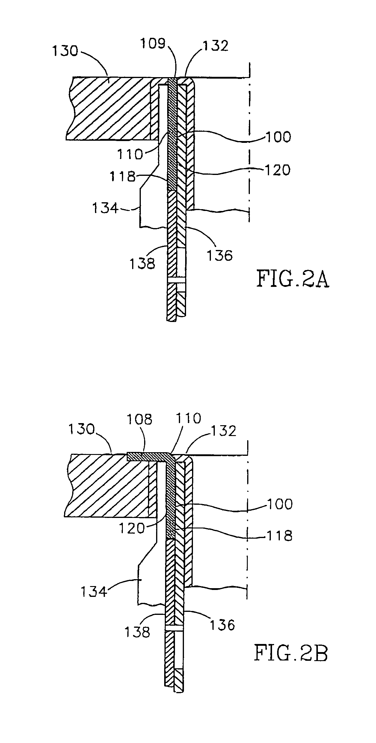
[0095]A spike element supports one or more opposing spikes, for example spikes 118 and 108 as shown. Spike 108 is shown with a sharp tip 109, for penetrating a graft vessel, as will be explained below with respect to FIG. 2.

[0096]A parti...


PUM


Abstract

An anastomosis connector comprises a plurality of ring segments (106), together defining a radially expandable ring-like shape (106) having a lumen; at least one pivot bar (114) coupled to at least one of said ring segments (106); at least one spike (109) mounted on said pivot bar (114) and rotatable around said pivot bar (114), wherein radial deformation of said ring-like shape (106) does not substantially directly affect said spike (109) rotational position.

Description

RELATED APPLICATIONS[0001]The present application is also a continuation-in-part of Ser. No. 09 / 936,789 filed Sep. 17, 2001, which is a 371 of PCT / IL99 / 00674 filed Dec. 9, 1999, which is a continuation-in-part of Ser. No. 09 / 936,806 filed Sep. 17,2001 which is a 371 of PCT / IL99 / 00670 filed Dec. 8, 1999 which is a continuation-in-part of Ser. No. 09 / 701,531 filed Nov. 28,2000, which is a 371 of PCT / IL99 / 00284. The present application is also a continuation-in-part of Ser. No. 09 / 701,523 filed Nov. 28, 2000 which is a 371 of PCT / IL99 / 00285, filed May 30, 1999.FIELD OF THE INVENTION[0002]The present invention relates to anastomosis connectors and especially to anastomosis connectors having a low profile.BACKGROUND OF THE INVENTION[0003]Various types of anastomosis connectors, for connecting two blood vessels, have been suggested in the art.[0004]One drawback of some connectors is their non-trivial profile, i.e., the connectors project outside of the volume defined by the anastomosis re...

Claims


Application Information

Patent Timeline
Patent Type & Authority Patents(United States)
IPC IPC(8): A61B17/04A61B17/064A61B17/08A61B17/11A61B17/32A61B17/34
CPCA61B17/064A61B17/11A61B17/0644A61B17/32053A61B2017/0641A61B2017/1107A61B2017/1121A61B2017/1135A61B2017/3482
Inventor LOSHAKOVE, AMIRKILEMNIK, IDOKEREN, DVIRZIMET, NACHMAN
Owner BY PASS
Why Eureka
Try Eureka