
Foam matrix embolization device

a foam matrix and embolization technology, applied in the field of medical devices, can solve problems such as incomplete aneurysm embolization, and achieve the effect of improving the mechanical integrity of foam and improving the efficacy of a particular treatment modality

Inactive Publication Date: 2005-12-27
CODMAN & SHURTLEFF INC
View PDF36 Cites 128 Cited by
  • Summary
  • Abstract
  • Description
  • Claims
  • Application Information

AI Technical Summary

Benefits of technology

[0013]In accordance with yet another aspect of the present invention, there is provided an embolization device having an embolization coil and foam sleeve disposed about the coil periphery, which is radiopaque. The embolization device may be made visible under fluoroscopy by using an embolization coil made from a radiopaque material such as a platinum or tungsten alloy. Alternatively, the foam sleeve may be made radiopaque by incorporating a radiopaque filler material such tantalum or tungsten powder or a radiopaque iodine commonly used in contrast media such as RENOGRAFFIN. This radiopaque material aids in the visualization of the embolization device during the medical procedure.
[0014]In still another aspect of the present invention there is provided an embolization device that comprises an embolization coil and a foam sleeve bonded to the coil. The embolization coil may contain reinforcing fiber or fibers that are secured in at least two locations and extend through the lumen of the coil to reduce coil stretching. Alternatively, the foam sleeve may contain reinforcing material dispersed throughout the foam, such as long fibers to resist stretching or short fibers or particles to improve sponge mechanical integrity.
[0018]In another aspect of the present invention there is provided an embolization device, which takes the form of an elongated flexible foam. The foam may take the form of a hydrogel. The foam may be used to deliver therapeutic agents to improve the efficacy of a particular treatment modality.
[0019]In yet another aspect of the present invention there is provided an embolization device, which takes the form of an elongated flexible cylindrical foam. To improve the mechanical integrity of the foam, the foam may contain reinforcing materials. Reinforcing materials may take the form of long fiber or fibers incorporated within the foam or short fibers or particles dispersed throughout the foam.
[0020]In still another aspect of the present invention there is provided an embolization device, which takes the form of an elongated flexible foam. The foam may be made visible under fluoroscopy by incorporating a radiopaque filler material such tantalum or tungsten powder or a radiopaque iodine commonly used in contrast media such as RENOGRAFFIN. This radiopaque material aids in the visualization of the embolization device during the medical procedure.

Problems solved by technology

These balloons do not generally conform to the aneurysm space thereby leaving unoccupied space leading to an incomplete aneurysm embolization.
Often times a balloon valve may leak thereby causing other balloons to shift position, which may in turn, occlude the parent artery leading to severe complications.

Method used


Image

  • Foam matrix embolization device
  • Foam matrix embolization device
  • Foam matrix embolization device

Examples


Embodiment Construction

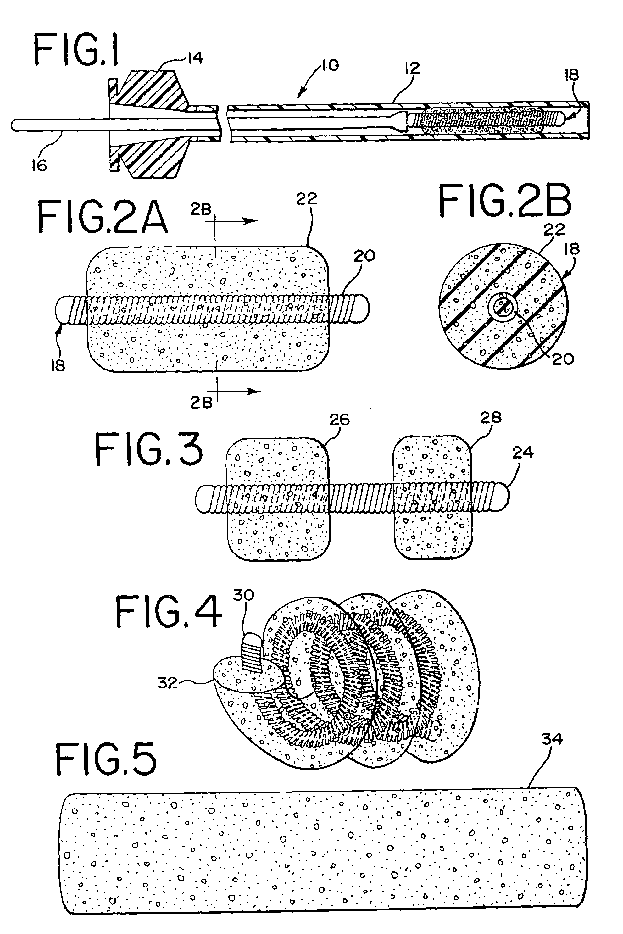
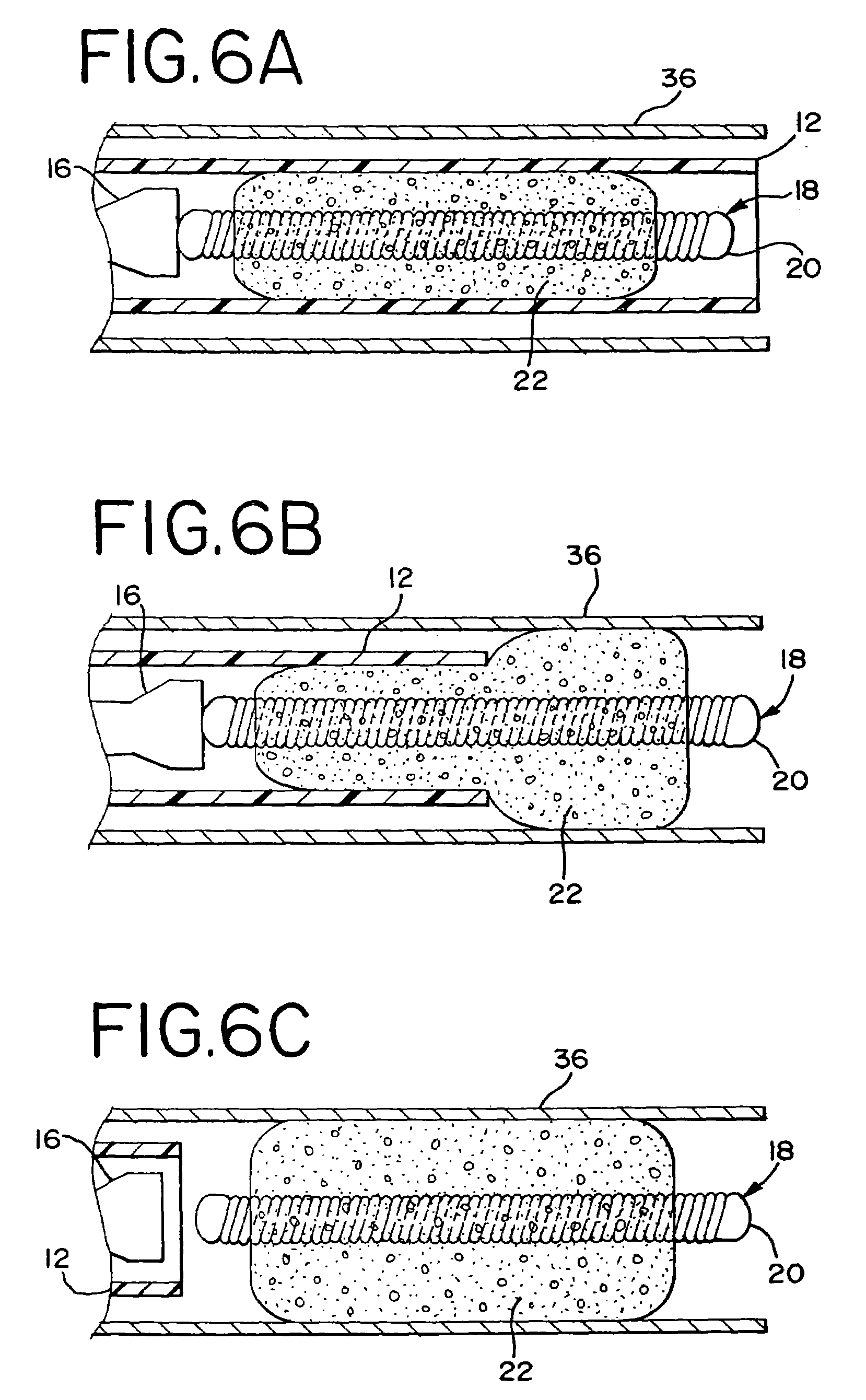
[0032]FIG. 1 illustrates a first embodiment of the vascular embolization system 10. The vascular embolization system 10 includes a catheter 12, having a proximal hub 14, push rod 16 and embolization device 18. Embolization device 18 is disposed within the lumen at the distal section of catheter 12. Push rod 16 is slidably disposed within the lumen of catheter 12, proximal to embolization device 18.

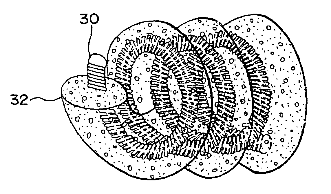
[0033]FIGS. 2A and 2B show axial and cross sectional views of embolization device 18. The embolization device 18 comprises an embolization coil 20 surrounded by a foam sleeve 22. The embolization coil 20 is of the type commonly used to reduce or embolize a particular blood vessel. Depending on the flexibility needed and catheter system utilized the embolization coil 20 ranges in diameter from about 0.002 inches to 0.150 inches with a preferred range of about 0.006 inches to 0.052 inches. Materials used to make the embolization coil 20 include polymers, metals or composites in filament form...


PUM


Abstract

The present invention relates to a medical device for placement at a predetermined location within a passageway of the human body, and more particularly, relates to a flexible expandable embolization device which may be delivered by a catheter to a pre-selected position within a blood vessel to thereby embolize a blood vessel or a blood vessel defect, such as an aneurysm or fistula.

Description

CROSS-REFERENCE TO RELATED APPLICATION(S)[0001]This patent application is a continuation of U.S. patent application Ser. No. 09 / 663,768, filed on Sep. 18, 2000, now U.S. Pat. No. 6,723,108, entitled, “Foam Matrix Embolization Device.”BACKGROUND OF THE INVENTION[0002]1. Field of the Invention[0003]The present invention relates to a medical device for placement at a predetermined location within a passageway of the human body, and more particularly, relates to a flexible embolization device which may be delivered by a catheter to a pre-selected position within a blood vessel to thereby embolize a blood vessel or a defect in a blood vessel, such as an aneurysm or fistula.[0004]2. Description of the Prior Art[0005]For many years flexible catheters have been used to place various devices within the vessels of the human body. Such devices include dilatation balloons, radiopaque fluids, liquid medications and various types of occlusion devices such as balloons and embolic coils. Examples o...

Claims


Application Information

Patent Timeline
IPC IPC(8): A61B17/12
CPCA61B17/12022A61B17/12145A61B17/1215A61B17/12154A61B17/12163A61B17/1219A61B2017/00893A61B2017/1205
Inventor JONES, DONALD K.MITELBERG, VLADIMIR
Owner CODMAN & SHURTLEFF INC
Learn More