
Power generating apparatus

Inactive Publication Date: 2005-12-27
EBARA CORP
View PDF21 Cites 42 Cited by
  • Summary
  • Abstract
  • Description
  • Claims
  • Application Information

AI Technical Summary

Benefits of technology

[0015]Thus, when the DC power supply voltage of the inverter device becomes equal to or exceeds the full-wave rectification voltage of the commercial AC power supply system, the interconnection switch is closed at the time of stating of the power generator. Accordingly, no current flows from the commercial power supply system into the inverter device even if the interconnection switch is closed. Therefore, no overcurrent flows in power switching elements of the inverter device from the commercial power supply system, and no overcurrent trip occurs. Thus, operation of interconnection can smoothly be performed.
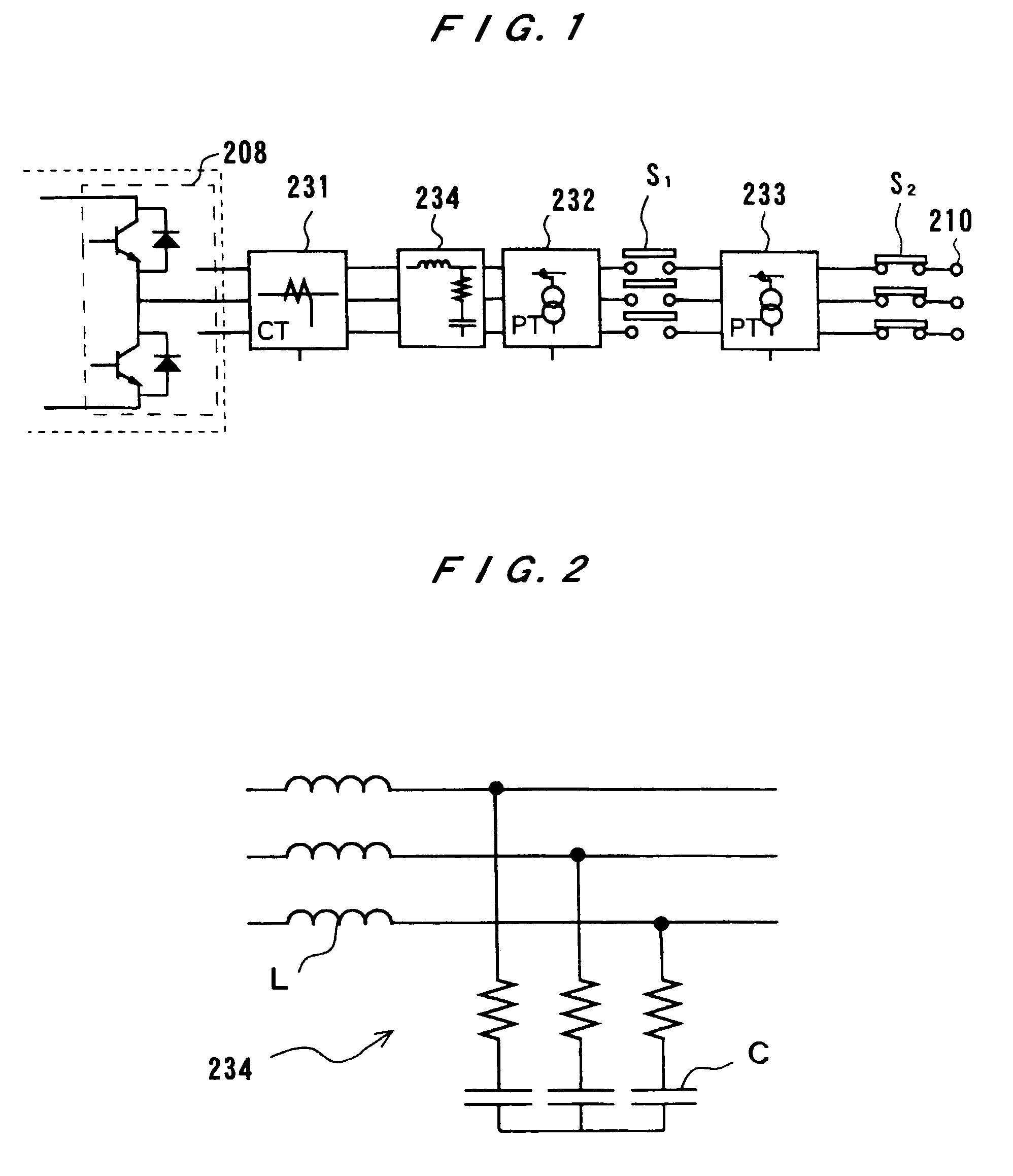
[0017]Thus, after the power generating apparatus is started, an output voltage of the inverter device is inputted through the active filter having simulated properties of the filter circuit, which comprises a reactor, into the interconnection control part. Accordingly, an output voltage waveform of the inverter device that will be outputted from the filter circuit can be detected in a state in which the interconnection switch is opened. A voltage PID control is performed so that the voltage waveform accords with the voltage of the commercial power supply system, and then the interconnection switch is closed. Thus, stable operation of interconnection can be performed.

Problems solved by technology

Accordingly, an inrush current is produced to cause a failure of interconnection.
However, it is difficult to precisely detect whether the voltages of the inverter device and the commercial power supply system are identical with each other.
Therefore, an overcurrent trip may occur and interfere with operation of the power generating apparatus.

Method used


Image

  • Power generating apparatus
  • Power generating apparatus
  • Power generating apparatus

Examples


Embodiment Construction

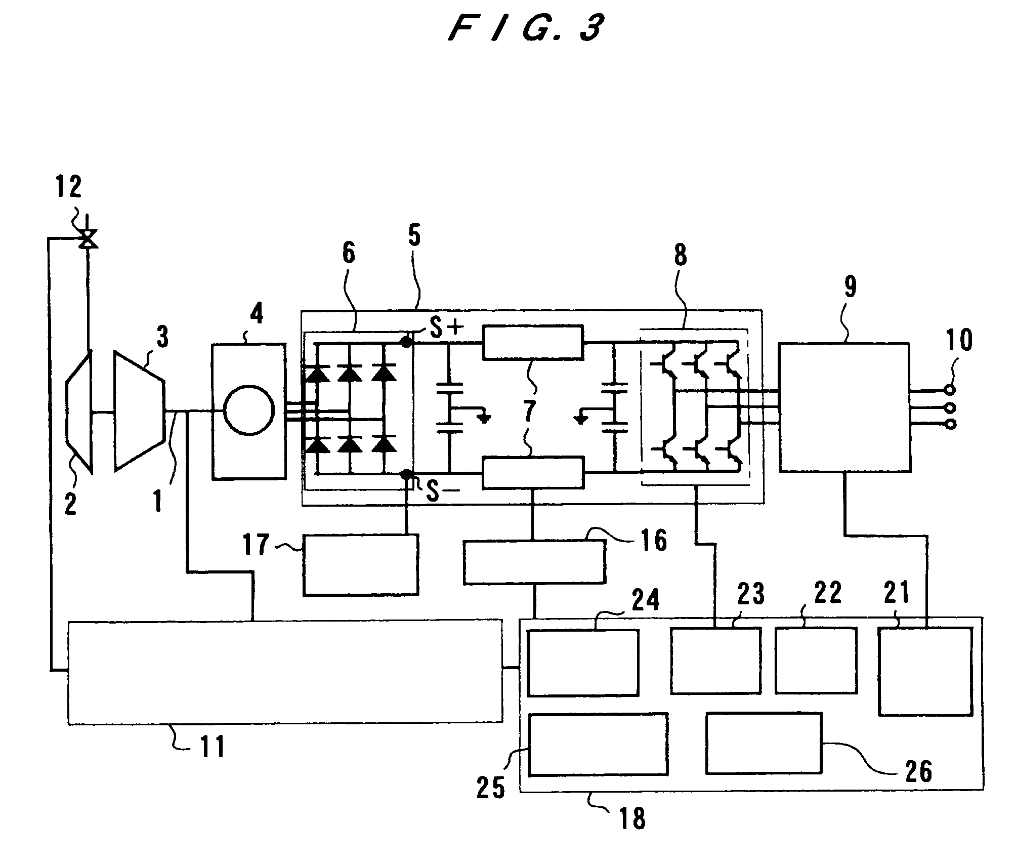
[0032]A power generating apparatus according to embodiments of the present invention will be described below with reference to FIG. 3 through 7.

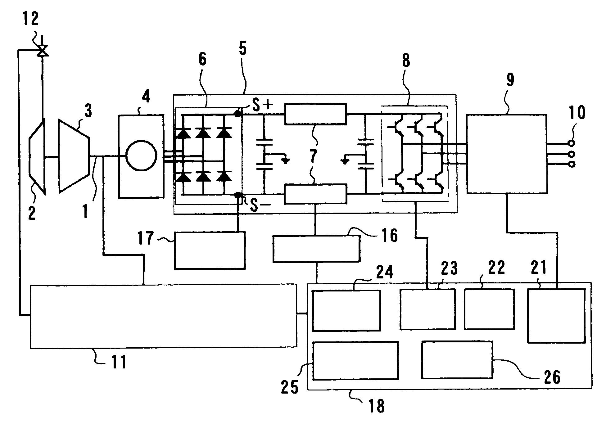
[0033]FIG. 3 is a block diagram showing a gas turbine power generating apparatus according to a first embodiment of the present invention. The gas turbine power generating apparatus can generate a large amount of electric power with a compact structure by ultrahigh-speed rotation of a gas turbine engine and a power generator coupled directly to the gas turbine engine. The gas turbine power generating apparatus has a rotational shaft 1, a gas turbine rotor 2 attached to the rotational shaft 1, a compressor rotor 3 attached to the rotational shaft 1, and a power generator 4. Specifically, the gas turbine power generating apparatus includes a gas turbine engine (driving source) having the gas turbine rotor 2, which is rotated at an ultrahigh rotational speed by combustion of a mixture of air and fuel, and a compressor for compressing air to be ...


PUM


Abstract

A power generating apparatus has a power generator 4 for generating AC power, a gas turbine engine 2 for driving the power generator 4, and an inverter device 5 for converting the AC power into commercial AC power. The power generating apparatus includes an interconnection switch S1 for connecting an output of the inverter device 5 with a commercial AC power supply system, a first voltage detector 46 for detecting a DC power supply voltage Vdc-in of the inverter device 5, and a second voltage detector 33, 45 for detecting a full-wave rectification voltage of the commercial AC power supply system. The power generating apparatus also includes an interconnection control part 18 for closing the interconnection switch S1 when the DC power supply voltage of the inverter device 5 exceeds the full-wave rectification voltage of the commercial AC power supply system.

Description

BACKGROUND OF THE INVENTION[0001]1. Field of the Invention[0002]The present invention relates to a small-sized power generating apparatus such as a gas turbine power generating apparatus, and more particularly to a method of operating such a power generating apparatus.[0003]2. Description of the Related Art[0004]Recently, the electric power market has been liberalized under deregulations of electric power. Accordingly, power supplies that can be locally distributed have been attracted considerable attention. Small-sized gas turbine power generating apparatuses have been employed as such power supplies. In the gas turbine power generating apparatus, fuel and compressed air are supplied to a gas turbine engine to rotate the gas turbine engine at an ultrahigh rotational speed of, for example, 100,000 rpm. When the gas turbine power generating apparatus is thus operated, a power generator, which is coupled directly to the gas turbine engine, generates alternating-current (AC) power havi...

Claims


Application Information

Patent Timeline
IPC IPC(8): H02J3/38H02J3/40
CPCH02J3/40
Inventor MCKELVEY, TERENCEMARUI, EISHIMIYAMOTO, MASAHIROFURUYA, TAIKATAOKA, TADASHISATO, MOTOYASUISHIHARA, SEIICHIOZAWA, TAKAHIDEKINOSHITA, NOBORUZHENG, SHAOJUN
Owner EBARA CORP
Learn More