Method and system for distributed video compression in personal computer architecture

Inactive Publication Date: 2005-12-27
HEWLETT PACKARD DEV CO LP
View PDF13 Cites 14 Cited by
  • Summary
  • Abstract
  • Description
  • Claims
  • Application Information

AI Technical Summary

Benefits of technology

[0007]The present invention is directed to a video compression system for a computer that distributes processing responsibility between the computer's central processing unit and co-processing resources. In this way, it avoids the costs associated with dedicated compression hardware while still allowing compression / decompression to occur in, or near, real-time. It capitalizes, however, on the trend toward integrating video capture capabilities into the video controller cards, in the preferred embodiment. Specifically, the video card is modified to include a motion estimation unit, which generates motion information describing inter-frame changes in the video data. The card then uses this motion information to perform motion-compensated temporal filtering on the video data before it is passed to the CPU, which performs the inter-frame and / or intra-frame compression. In a preferred embodiment, the temporal filtering reuses the video controller's data path and frame buffer, both of which are also used to perform frame processing for the video display.
[0011]In general, according to another aspect, the invention also features a video preprocessing and compression system for a computer. The system comprises a motion estimation unit that generates motion information describing inter-frame changes in video data. A video frame processing unit performs motion-compensated temporal filtering on frames of the video data using the motion information. The processed data is then passed to the central processing unit, which performs inter-frame and / or intra-frame compression with reference to the motion information. As a result of this division of processing, resources on a video capture card may be utilized to reduce the CPU's processing burden and video controller resources reused for compression.

Problems solved by technology

In order to optimize the bit rate / resolution trade-off, many compression / decompression algorithms are computationally intensive, especially when considering their real-time operation.
There are technical and / or practical problems associated with each of the typical approaches.
The CPU is generally not well optimized for handling pixel-granularity video data.
Dedicated compression hardware utilizes these SIMD architectures and consequently works well, but is typically too expensive for the consumer / small business environments.
Finally, the compression co-processor approach provides a better price / performance trade-off but is still an expensive hardware upgrade in an increasingly commoditized computer market.

Method used


Image

  • Method and system for distributed video compression in personal computer architecture
  • Method and system for distributed video compression in personal computer architecture
  • Method and system for distributed video compression in personal computer architecture

Examples


Embodiment Construction

[0019]A description of preferred embodiments of the invention follows.

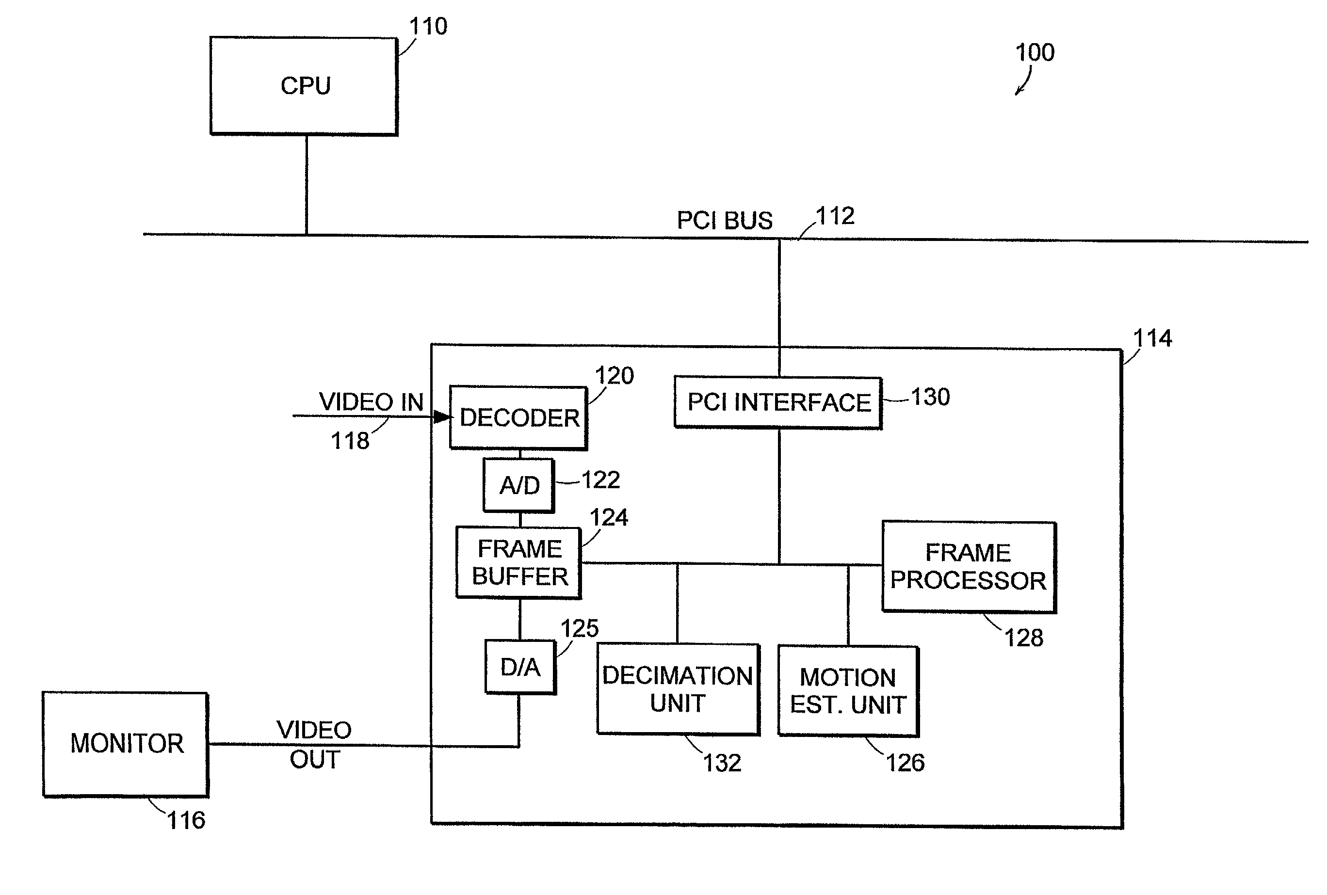
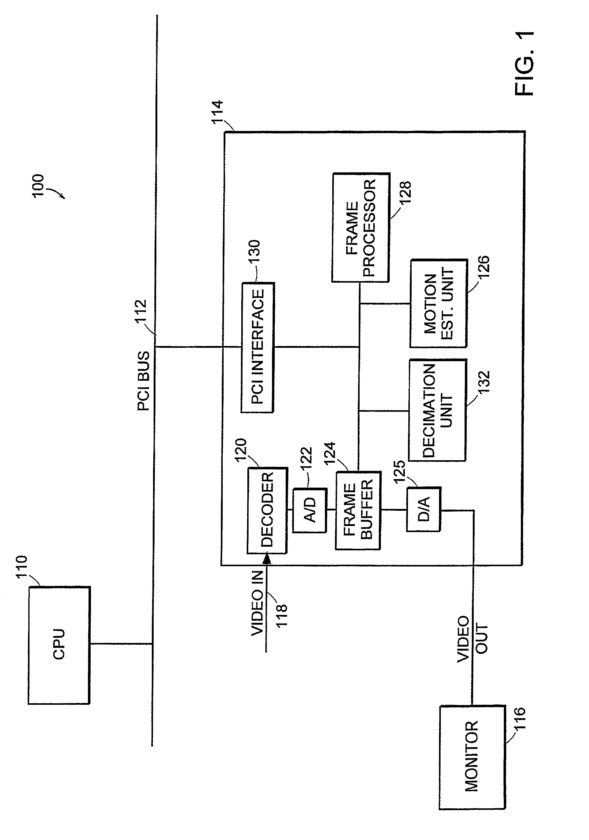
[0020]FIG. 1 illustrates a computer system 100 that performs video preprocessing and compression in accordance with the principles of the present invention. Generally, as is common in many personal computer systems, a central processing unit (CPU) 110 represents the computation core of the computer. It connects to peripheral devices via a bus 112, which in the preferred embodiment is a peripheral component interconnect (PCI) protocol bus.

[0021]A video capture / controller card 114 communicates with and is controlled by the CPU 100 via the PCI bus 112, principally to convert video data into the format needed to drive the monitor 116. Specifically, data and instructions are received from the CPU 100 through PCI interface 130, and the data is stored in the frame buffer 124. Frame processor 128 operates on this data to generate pixel frame data appropriate for display on the monitor 116 after digital-to-analog conversio...


PUM


Abstract

A method and system for compressing video data in a computer has video processing that is distributed between preprocessing hardware in a video capture / controller card and a central processing unit of the computer. Frames of video data are passed to a motion estimation unit of the preprocessing hardware. This unit generates motion information describing inter-frame changes in the video data. Next, motion-compensated temporal filtering is performed on the frames of video data using the motion information. A video frame processing unit of the controller card, used for processing video data to the monitor, is reused for the temporal filtering of the input video data. Finally, the temporally-filtered video data is passed to the central processing unit, which performs inter-frame and / or intra-frame compression with reference to the motion information. In this way, motion-compensated temporal filtering is performed, thus removing the associated noise without adding to the CPU's processing burden, but the costs associated with dedicated compression hardware are avoided by relying on the video capture capabilities in the video controller card.

Description

RELATED APPLICATION[0001]This application is a continuation of U.S. application Ser. No. 09 / 105,059, filed Jun. 26, 1998. Now U.S. Pat. No. 6,411,651 The entire teachings of the above application are incorporated herein by reference.BACKGROUND OF THE INVENTION[0002]Computer systems rely on video compression and decompression for video storage / playback and video teleconferencing applications. The objective typically is to reduce the number of transmitted or stored bits needed to represent the original signal while minimizing the loss in resolution when decompressed. By balancing these competing factors, video teleconferencing and other real-time video transfer, for example, can be accomplished within the bandwidth restrictions imposed by local area networks, wide area networks, internetworks, and circuit-switched telephone networks, such as integrated services data network (ISDN) lines or standard telephone lines (POTS).[0003]In order to optimize the bit rate / resolution trade-off, ma...

Claims


Application Information

Patent Timeline
IPC IPC(8): H04N7/26H04N7/50
CPCH04N21/4143H04N19/61H04N19/42
Inventor ROSE, ROBERT C.ADILETTA, MATTHEW J.HO, SAMUEL W.
Owner HEWLETT PACKARD DEV CO LP
Why Eureka
Try Eureka