Matched filter, filtering method and digital broadcast receiver using the same

a filtering method and filtering technology, applied in the field of digital broadcast receivers, can solve the problems of bit detection error at the receiver, inter-symbol interference, and the inability to realize the shape of the receiving filter having an infinite time delay, and achieve the effect of increasing the circuit complexity and deteriorating the snr performan

Inactive Publication Date: 2005-12-27
LG ELECTRONICS INC
View PDF7 Cites 72 Cited by
  • Summary
  • Abstract
  • Description
  • Claims
  • Application Information

AI Technical Summary

Benefits of technology

[0047]To solve the above problems, an object of the present invention is to provide a digital passband matched filter, filtering method, and a digital broadcast receiver using the same, which can supplement the drawbacks caused by the structural characteristics of the conventional fixed baseband / passband matched filter such as a deterioration of the SNR performance and increase of the circuit complexity by allowing the carrier wave frequency to automatically adapt to the carrier wave frequency offset.

Problems solved by technology

In theory, receiving filters have characteristics of a rectangular band, and cannot realize the shape of a receiving filter having an infinite time delay.
Thus, the detecting procedure in a system having such characteristics is quite sensitive to even a slight timing error, and although an inter-symbol influence can be avoided at an accurate sampling time, inter-symbol interference occurs where a slight error exists.
Thus, in a digital transmission system such as an HDTV, a transmission signal causes a bit detection error at the receiver due to the signal distortion generated due to passing through a channel, interruption by an NTSC signal, or distortion caused by a transmission / receipt system.
In particular, the radio wave of the signal traveling through multi-paths causes an inter-symbol interference, which becomes a major cause of bit detection errors.
First, the digital demodulator shown in FIG. 2a that uses a fixed baseband matched filter of two channels and a re-sampler of two channels is compatible with the OFDM / QAM / QPSK demodulation method but incompatible with any of the VSB demodulation methods. To be specific, if a baseband matched filter is used, the VSB demodulation method having single side band (SSB) characteristics causes a frequency distortion around DC, as shown in FIGS. 3a and 3b, when demodulating a passband signal to a baseband signal. Moreover, circuit complexity drastically increases due to a requirement of the fixed baseband matched filter of two channels and the re-sampler of two channels.
Such a frequency distortion deteriorates an SNR performance of the demodulator, and places a burden on the channel equalizing section.
Such a spectrum distortion of the passband digital output signal causes an inter-symbol interruption, thereby resulting in an increase of the additive white Gaussian noise (AWGN), which is a major cause of bit detection errors as well as a deterioration of a bit error rate (BER) and a signal to noise ratio (SNR) as shown in FIG. 5.
Therefore, a demodulator including a fixed passband matched filter is incompatible with any of the VSB (OFDM) / QAM / QPSK demodulation methods.
In particular, the circuit complexity drastically escalates subsequent to deterioration of the SNR performance and the number of taps of the matched filter, as shown in FIG. 5.
Thus, inconvenience still exists to determine what kind of matched filter should be employed depending on the demodulating method: the fixed passband matched filter 202c or the fixed baseband matched filter 205c.

Method used


Image

  • Matched filter, filtering method and digital broadcast receiver using the same
  • Matched filter, filtering method and digital broadcast receiver using the same
  • Matched filter, filtering method and digital broadcast receiver using the same

Examples


first embodiment

of the Present Invention

[0102]FIG. 7 is a configuration block diagram of a multimedia broadcast receiver in accordance with Example 1 of the present invention. The multimedia broadcast receiver comprises: a pre-processing section 301 digitalizing an IF analog signal and outputting a passband digital signal; a digital passband matched filter 303 filtering a digital signal by automatically adapting a passband digital signal outputted form the pre-processing section 301 to a fed back carrier frequency; a post-processing section 304 processing an output of the digital passband matched filter 303; and a carrier wave recovery section 302 transiting the passband digital signal into a baseband digital signal by recovering the carrier wave from the passband digital signal outputted from the post-processing section 304 and feeding back the recovered carrier frequency to the digital passband matched filter 303.

[0103]FIG. 8 is a configuration block diagram in accordance with the first example o...

second embodiment

of the Present Invention

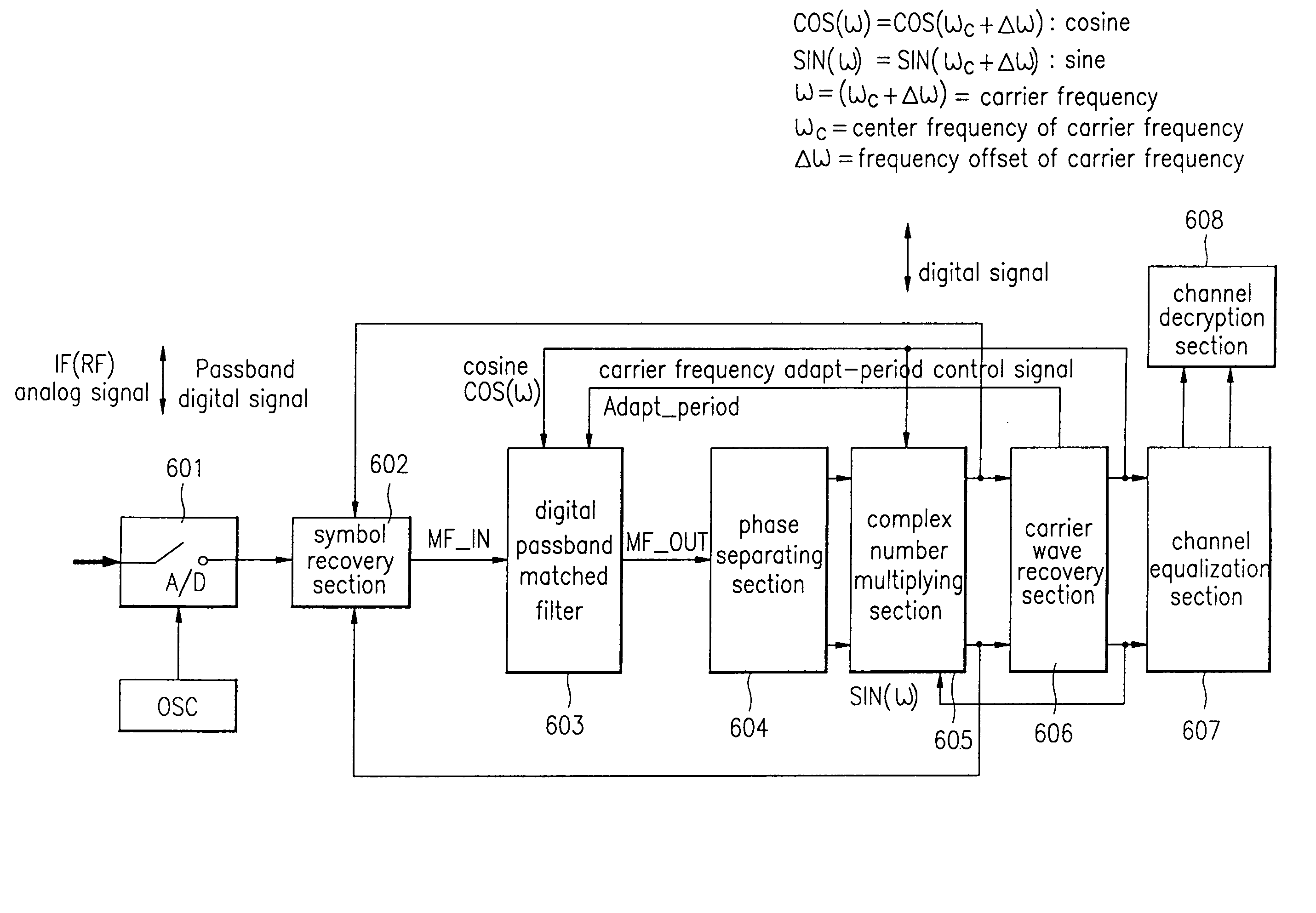
[0147]FIG. 16 is a structural diagram of a multimedia digital broadcast receiver according to a second embodiment of the present invention, which comprises a pre-processing section 501 for outputting the passband digital signal; a carrier wave section 502 generating the cosine COS having the carrier frequency as the center frequency and the carrier frequency adapt-period Adapt—Period control signal; the cosine COS outputted from the carrier wave recovery section 502; and a digital passband matched filter section 503 for outputting the carrier frequency by automatically adapting from the pre-processing section 501 according to the carrier frequency adapt-period control signal Adapt—Period to the post-processing section 504.

[0148]FIG. 17 is a structural diagram of a digital demodulator according to the second embodiment of the present invention equipped with the carrier recovery section 502 generating the digital passband matched filter 503 automatically adapti...


PUM


Abstract

A digital passband matched filter is automatically adapted to a carrier wave ω in accordance with a frequency offset of the carrier wave, to obtain a passband digital signal having no frequency distortion due to the frequency offset. Thus, a receiver in which drawbacks such as decrease of SNR and increase of circuit complexity caused by the fixed baseband/passband matched filter is obtained. Since a cosine wave generating section operates in a carrier wave frequency restoring mode and a carrier wave frequency adaptive mode, respectively, a single cosine wave ROM table can be used regardless of the respective operating modes, thereby reducing circuit complexity. Since the digital passband matched filter acts to renew the filter coefficients adapted to the carrier wave adaptive mode only, power consumption required to operate the filter can be minimized.

Description

BACKGROUND OF THE INVENTION[0001]1. Field of the Invention[0002]The present invention relates to a digital broadcast receiver, and more particularly to a matched filter of a digital passband which is variable depending on the recovery result of a carrier wave, and a filtering method and a digital broadcast receiver using the same.[0003]2. Description of the Related Art[0004]A digital broadcast receiving technology currently being developed through diverse media (ground wave, cable, satellite) is oriented toward an integrated system structure for integrated digital broadcasting.[0005]In particular, the transmission system of a digital TV (e.g., HDTV) transmitting data at a high bit rate of more than about 20 Mb / s through band-limited 6 MHz requires a modulation / demodulation method of high band efficiency.[0006]Further, the transmission system of a digital TV further requires a channel equalizer to compensate for non-ideal characteristics of a channel such as a symbol / carrier wave for...

Claims


Application Information

Patent Timeline
Patent Type & Authority Patents(United States)
IPC IPC(8): H04N7/015H03D1/00H04L27/00H04L27/06
CPCH04L27/06H04L2027/003H04L2027/0042H04L2027/0057H04L2027/0063H04N7/015
Inventor AHN, KEUN HEE
Owner LG ELECTRONICS INC
Why Eureka
Try Eureka