
System and method for measuring RF radiated emissions in the presence of strong ambient signals

a technology of ambient signal and rf radiation, which is applied in the field of system and method for measuring ambient signal strength, can solve the problems of personal computer lock-up, weak rf radiation emitted by the electronic device under test, and the increasing vulnerability of modern electronic devices to such rf interferen

Inactive Publication Date: 2005-12-27
SCI APPL & RES ASSOCS
View PDF6 Cites 11 Cited by
  • Summary
  • Abstract
  • Description
  • Claims
  • Application Information

AI Technical Summary

Benefits of technology

"The patent describes a system and method for extracting radiated emissions from an electronic device in the presence of ambient signals. The system includes two receivers that detect the ambient signals and the radiated emissions. The first receiver demodulates and digitizes the ambient signals and the radiated emissions, while the second receiver detects primarily the ambient signals. An adaptive filter is used to suppress the ambient signals that are correlated between the first and second receivers. The technical effect of this system is to accurately measure the radiated emissions from the electronic device while minimizing interference from the ambient signals."

Problems solved by technology

The trend toward small, low power, high density electronics has made modern electronic devices increasingly more susceptible to such RF interference.
For example, turning on a microwave oven near a personal computer may cause the personal computer to lock up, or radio frequency noise from an automobile ignition may introduce static in a nearby AM radio receiver.
Unfortunately the RF radiation emitted by the electronic device under test can be weaker than ambient field strengths emitted from local transmitters (e.g., signals from TV and radio stations).
Commercially available spectrum analyzers and receivers typically cannot differentiate between the RF radiation from the electronic device under test and the much stronger ambient signals.
However, the RF anechoic chamber test method is disfavored due to the necessity to procure and maintain expensive RF anechoic chambers.
Specifically, a three meter RF anechoic chamber may cost several hundred thousands of dollars and a ten meter chamber may cost well over a million dollars.
While this test method is not as sensitive as the anechoic chamber test method, it does accurately measure radiated emissions which are near or above certification levels.
However, the remote open area test site test method is disfavored due to the construction and maintenance costs of the remote outdoor test facility.
While the initial cost of a remote test site can be significantly lower than purchasing an anechoic chamber, the maintenance and operational cost of such remote outdoor test facility can be very high.
An additional problem is that as cites expand, these remote areas are more difficult to locate.
It is very difficult to find a location where the is no TV, radio, cell phones, police radios, and ham radios (to name a few).
In areas where this is possible, costs associated with bring personnel and equipment to and from this location is high.
If the frequency of the radiated emission is very close to or at the frequency of the ambient emission, then the urban open test site test method fails to separate and detect the radiated emission.
However, this method has limited accuracy for emission frequencies which are not clearly distinct from ambient frequencies.
Furthermore, this test method requires highly trained personnel as well as the use of highly sensitive spectrum analyzers.
This method cannot be used to certify electronic devices due to the limited accuracy thereof.
A major problem with this method is that the bandwidth required to separate these signals is not at the bandwidth specified by the regulatory agencies.
Therefore, this measurement technique cannot be used to measure the signal's strength.
Another problem with this method is that it can only be used when the emissions signal is not changing frequencies and it cannot be used when the emissions and ambient signals are very close in frequency.
However, this method can be used for limited pre-compliance testing and trouble shooting, such as during the process of searching, monitoring, and tracking radiated emission frequencies.
A major problem with this method is that it does not work if the electronic device's emissions are at the same frequencies, but lower, than the ambient signals.
Also, this method does not work if any ambient signals change frequency, which most do.
Another problem is that ambient signals, which change levels or turn on and off, can be incorrectly identified as the device's emissions.
The second location is sufficiently far away so that it does not detect the weak radiated emissions from the electronic device under test.
However, it cannot account for differences in two simultaneously received ambient signals caused by multi-path distortion.
Accordingly, the ambient signal cancellation is very unreliable.
Furthermore, this test method does not take into account the frequency drift and jitter between the two recording receivers thereby making signal alignment very difficult and time consuming.
This manual alignment process if very time consuming and error prone.
The ambient cancellation using subtraction test method additionally fails when the much stronger ambient signals are at the same frequency as the desired radiated emissions of the electronic device since most recording instruments do not have the adequate resolution and sensitivity to isolate the signal of interest by using simple subtraction.
Therefore, this test method is not used for compliance or pre-compliance testing because it is highly unreliable.

Method used


Image

  • System and method for measuring RF radiated emissions in the presence of strong ambient signals
  • System and method for measuring RF radiated emissions in the presence of strong ambient signals
  • System and method for measuring RF radiated emissions in the presence of strong ambient signals

Examples


Embodiment Construction

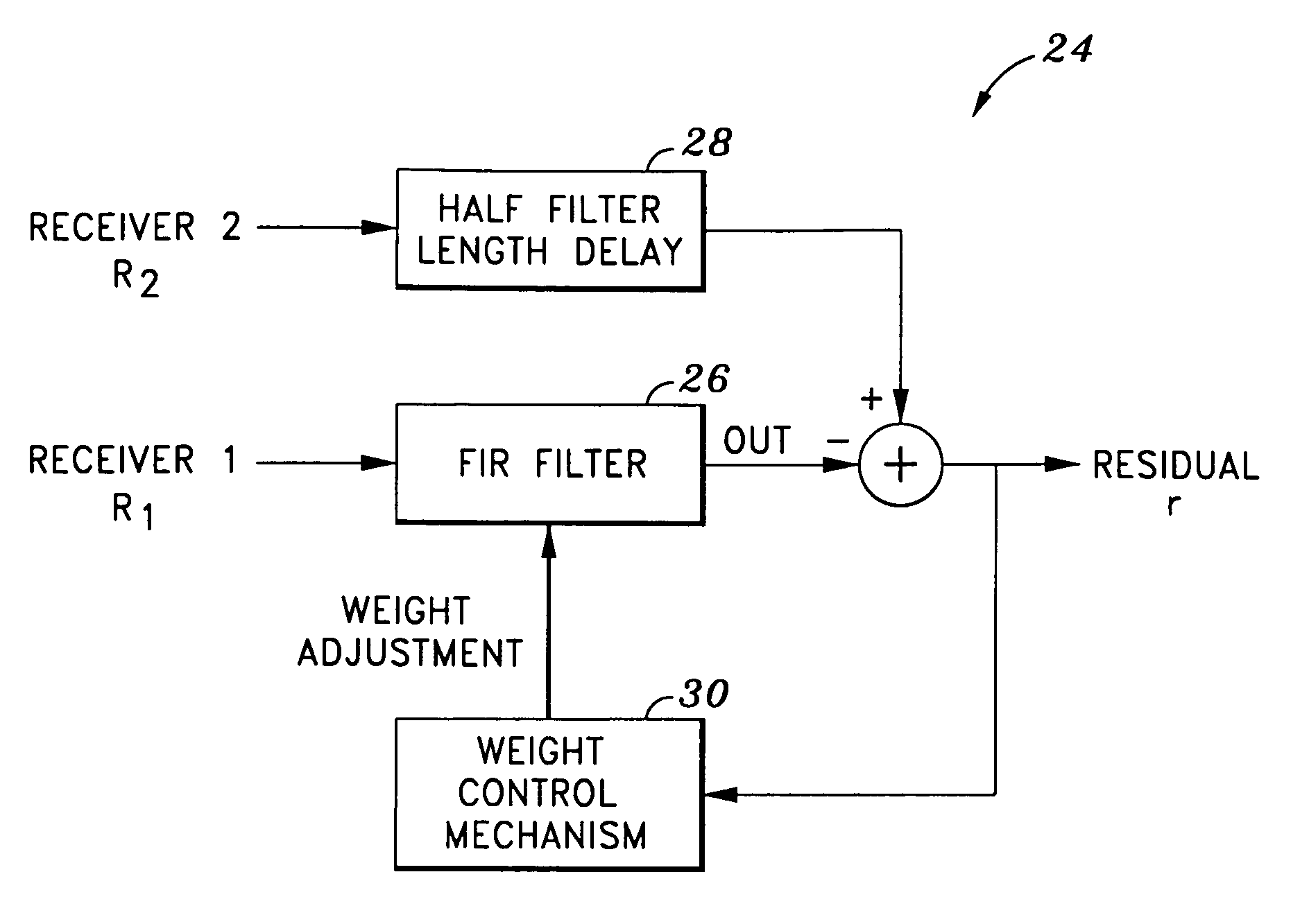
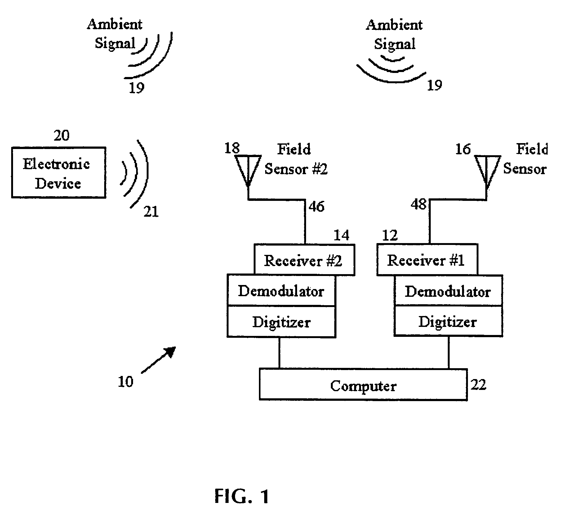
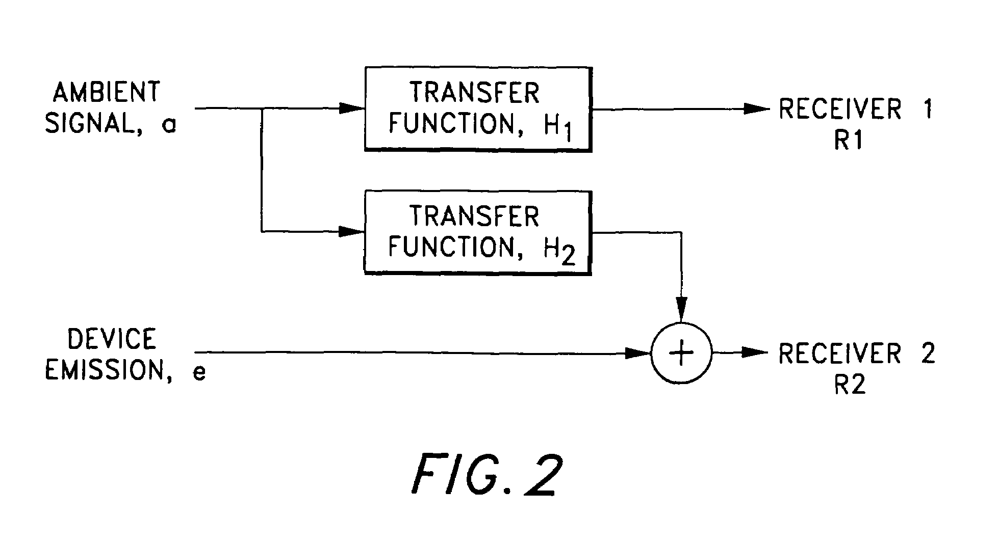
[0029]Referring now to the drawings wherein the showings are for purposes of illustrating a preferred embodiment of the present invention only, and not for purposes of limiting the same, FIG. 1 shows an ambient suppression test configuration 10 for radiated emissions testing. The test configuration 10 comprises a first receiver 12 and a second receiver 14. The first receiver 12 is in electrical communication with a first field sensor 16. Similarly, the second receiver 14 is in electrical communication with a second field sensor 18. As seen in FIG. 1, the first field sensor 16 and the second field sensor 18 are both disposed in a location whereat they may receive ambient RF signals 19. As will be recognized by those of ordinary skill in the art, the ambient RF signals 19 are typically RF electromagnetic radiation emitted by local transmitters. Such ambient RF signals 19 may be produced by local television and radio stations, cellular phones, citizens band radios, ham radios, civil ra...


PUM


Abstract

A system for suppressing ambient signals from a signal containing radiated emissions of a electronic device and ambient signals. The system comprises a first receiver operative to receive the ambient signals and the radiated emissions from the electronic device. The first receiver is operative to demodulate and digitize the ambient signals and the radiated emissions. The system further comprises a second receiver operative to receive primarily the ambient signals wherein the second receiver is time and frequency synchronized to the first receiver and operative to demodulate and digitize the ambient signals. A central computer is in electrical communication with the first and second receivers and is operative to store and process the ambient signals and the radiated emissions from respective ones of the first and second receivers. Accordingly, the central computer is configured as an adaptive filter operative to suppress the ambient signals correlated between the first and second receivers. Therefore, the radiated emissions from the electronic device are extracted thereby.

Description

CROSS-REFERENCE TO RELATED APPLICATIONS[0001]The present invention claims priority to Provisional Patent Application Ser. No. 60 / 119,157 entitled VIRTUAL CHAMBER MEASURING RF RADIATED EMISSIONS IN THE PRESENCE OF STRONG AMBIENT SIGNALS filed on Feb. 8, 1999, the disclosure of which is incorporated expressly herein by reference.BACKGROUND OF THE INVENTION[0002]The present invention generally relates to the area of electronic test equipment. More specifically, the present invention pertains to devices that are capable of measuring electromagnetic or radio frequency (RF) radiated emissions of electronic equipment in the presence of strong ambient signals.[0003]Electronic equipment radiates RF energy (i.e., RF radiated emissions) during normal operation that can interfere with nearby electronics. The trend toward small, low power, high density electronics has made modern electronic devices increasingly more susceptible to such RF interference. For example, turning on a microwave oven ne...

Claims


Application Information

Patent Timeline
Patent Type & Authority Patents(United States)
IPC IPC(8): H04B1/10
CPCH04B1/1027
Inventor MARINO, JR., MICHAEL A.
Owner SCI APPL & RES ASSOCS
Learn More