Speed and fluid flow controller

a fluid flow and controller technology, applied in the field of speed and fluid flow controllers, can solve the problems of increasing the electric current through the motor, the operation of the gas monitoring instrument is not predictable, and the method has a serious drawback

Inactive Publication Date: 2006-01-03
TELEDYNE DETCON INC
View PDF22 Cites 44 Cited by
  • Summary
  • Abstract
  • Description
  • Claims
  • Application Information

AI Technical Summary

Benefits of technology

[0007]In a system where motor speed is regulated by Pulse Width Modulation (PWM) of the motor drive voltage, the back-e.m.f. is sampled during intervals between the drive pulses applied to the motor. The invention improves such a system by sampling the-back-e.m.f. at a rate lower than the pulse rate of the modulated drive pulses. Back-e.m.f. sampling may occur only once for ten or 100 drive pulses, for example. The reduced sampling rate permits the duty factor of the drive pulses to approach 100 percent, thereby making efficient use of voltage sources such as batteries.
[0008]Advantageously, in an instrument that uses a microprocessor and analog-to-digital (A/D) converter to measure gas-concentration, the same microprocessor and converter can provide the

Problems solved by technology

When the flow through the system is not constant, the gas monitoring instrument is not predictable in its operation.
In a monitoring instrument having a positive-displacement pump driven by a direct current motor, an obstruction of the gas flow will result in an increased electric current through the motor.
However, this method has a serious drawback.
The uncertainty of the motor current

Method used


Image

  • Speed and fluid flow controller
  • Speed and fluid flow controller
  • Speed and fluid flow controller

Examples


Embodiment Construction

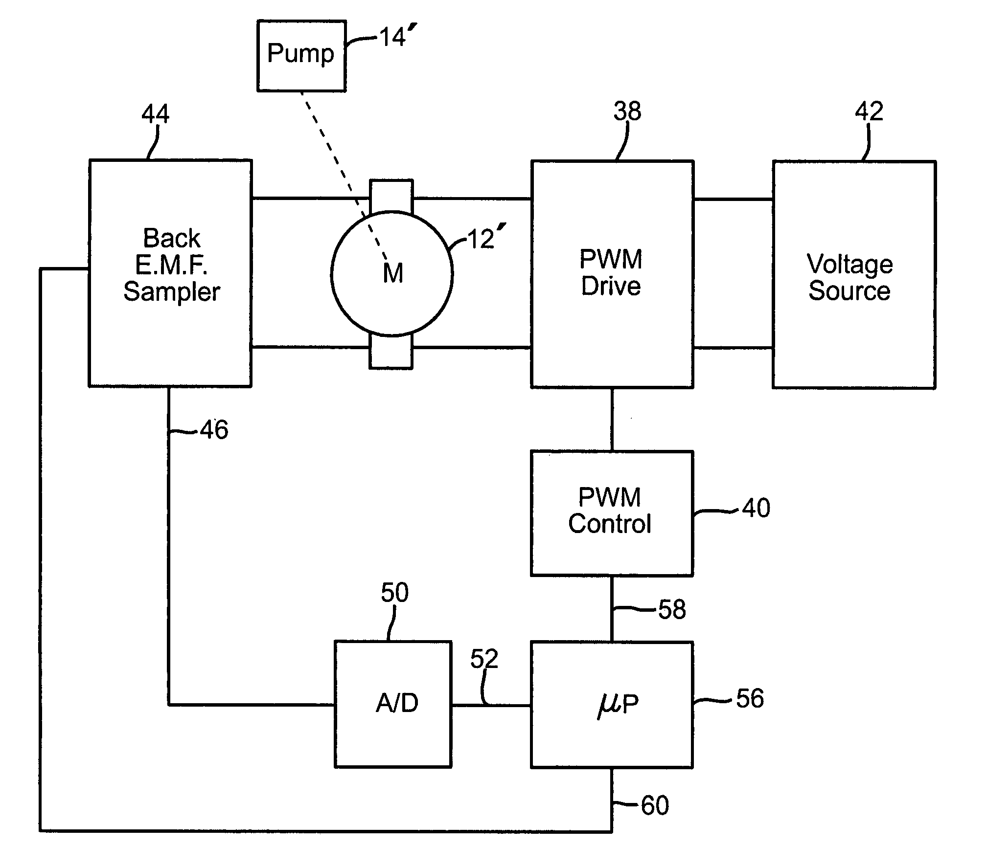
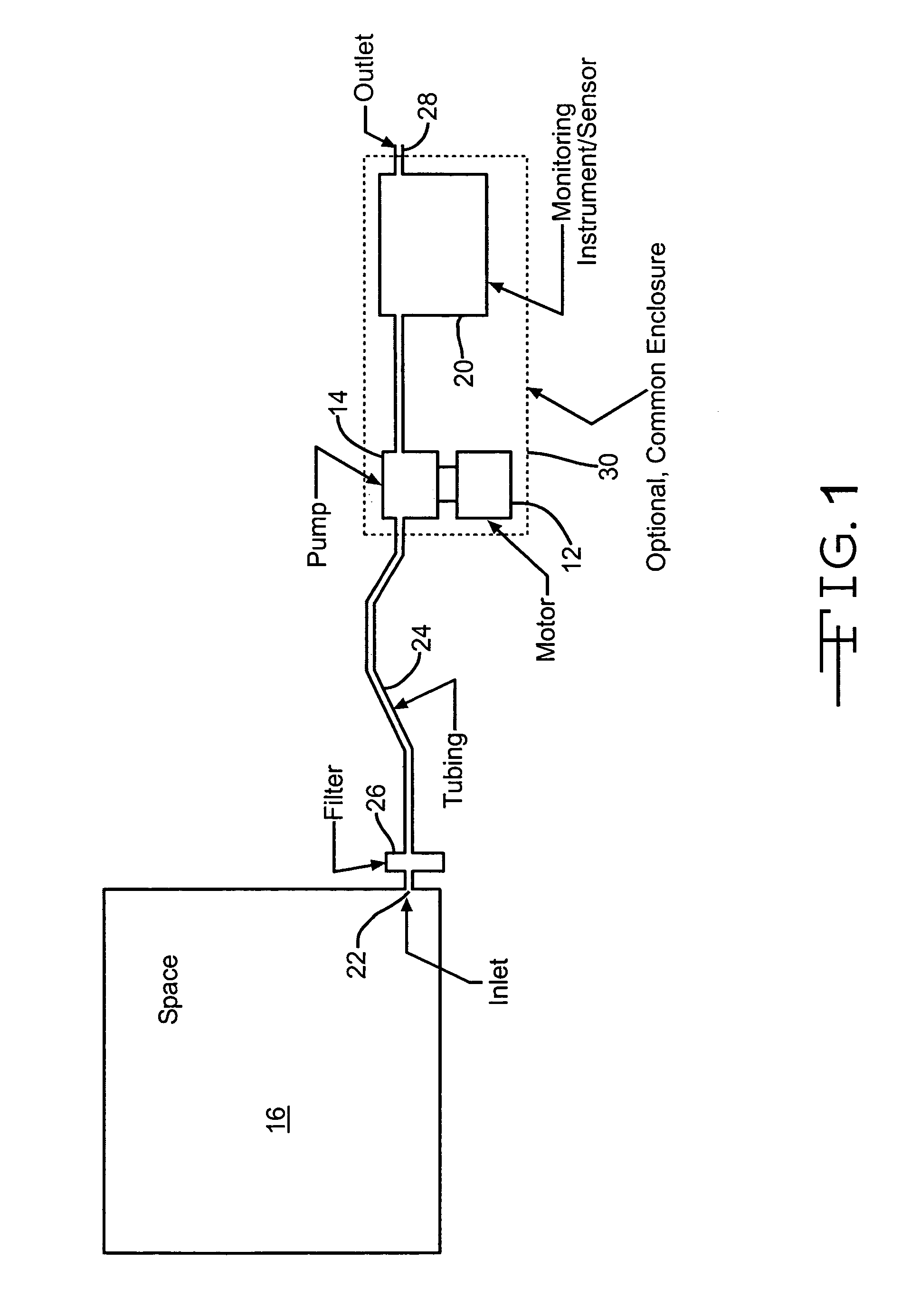
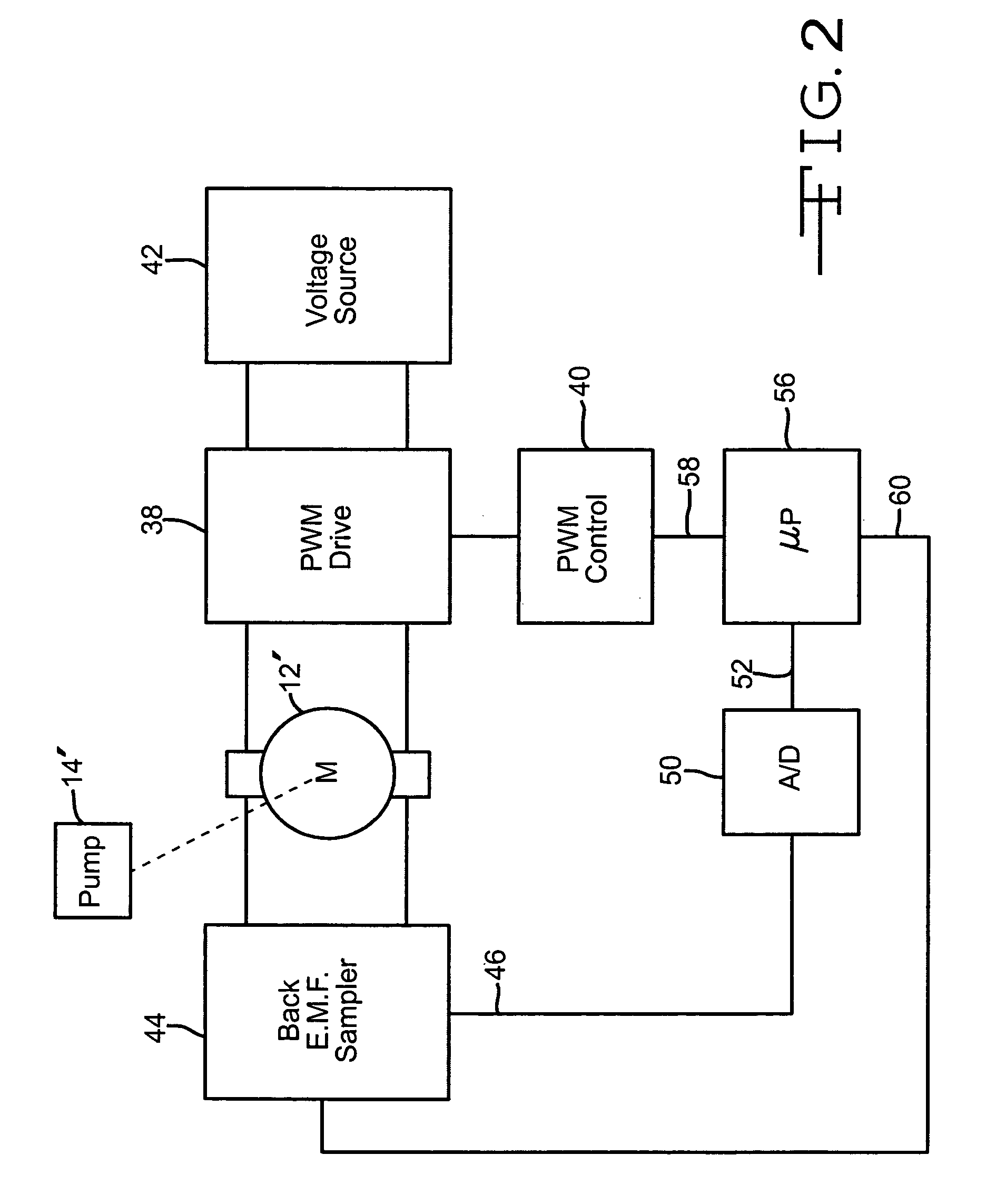
[0014]FIG. 1 is a schematic of part of a gas monitoring instrument 10 to which the present invention is applicable. The invention is not limited to a gas monitoring instrument, and the invention may be used to monitor other fluids, for example, liquids. The invention is merely illustrated using a gas monitoring instrument as an example of how the invention might be implemented. The gas monitoring instrument has an electrically powered motor 12 for driving a pump 14 to bring a sample of gas from a region or space 16, such as a room or pipe, to a sensor 20, so that the sample of gas can be tested for a contaminant. A gas inlet 22 or probe in the space 16 being tested is in gas communication with the monitoring instrument through flexible tubing 24, usually ranging from 1 meter to 30 or more meters in length. One or more filters 26 may be placed at the inlet and in the tubing to exclude particles and liquids, which could degrade the function of the tubing, the pump, or the instrument. ...


PUM


Abstract

A system and method for measuring fluid flow rate in a system where fluid is pumped, such as a gas monitoring instrument where gas is pumped from a space such as a room or enclosure through a conduit to a sensor. The flow of gas through a pump is determined by measuring motor back-e.m.f. which is proportional to motor speed. In a system where motor speed is regulated by pulse width modulation of the motor drive voltage, the back-e.m.f. is sampled during intervals between the drive pulses applied to the motor, and in a further aspect the sampling is done at selected, spaced-apart or infrequent intervals such as once for every ten or once for every hundred motor drive pulses. Advantageously, in an instrument that uses a microprocessor and analog-to-digital converter to measure gas-concentration, the same microprocessor and converter can provide the PWM control of the pump, in response to the back-e.m.f. generated by the pump motor between the drive pulses. The microprocessor compares the output of the analog-to-digital converter, corresponding to the back-e.m.f., which in turn corresponds to the pump motor speed, to a set-point value, representative of the desired pump motor speed. The processor then adjusts the PWM to control the pump motor to achieve and maintain the desired speed. As a result, in a gas monitor, the gas-flow rate may be maintained close to a desired gas flow rate regardless of the voltage supplied by the battery or other voltage source, regardless of the degree to which the gas is filtered, and under a wide range of operating conditions.

Description

CROSS REFERENCE TO A RELATED APPLICATION[0001]Applicant claims priority based on U.S. provisional patent application No. 60 / 384,688 filed May 31, 2002 and entitled “Speed and Fluid Flow Controller” which is incorporated herein by reference.BACKGROUND OF THE INVENTION[0002]In a basic gas monitoring instrument, an electrically powered motor drives a pump to bring a sample of gas from a region or space, typically via a flexible conduit or tubing, to a sensor so that the sample of gas can be tested for a contaminant. The flow rate is affected by the fluid dynamics of the system, which can change from time to time. When the flow through the system is not constant, the gas monitoring instrument is not predictable in its operation. Prior art systems operate the pump at a flow rate greater than required to insure that the minimum required flow rate is obtained. Accordingly, it would be desirable to provide a system wherein a minimum steady flow is maintained in a manner consuming only that ...

Claims


Application Information

Patent Timeline
IPC IPC(8): G01N7/00G01N19/10F04B49/06F04B49/20F04B51/00F04D15/00G01N1/24G05B11/26G05B21/02G05D7/06H02P6/18H02P7/29
CPCF04B49/20H02P7/29G05D7/0676H02P6/182F04D15/0066F04B2203/0209F04B2203/0213
Inventor BRISTOL, L. RODNEY
Owner TELEDYNE DETCON INC
Why Eureka
Try Eureka