Multi-heatsink integrated cooler

a multi-heatsink, integrated technology, applied in the field of cooling systems, can solve the problems of difficult to connect the housing directly one to the other, and the common airflow system is difficult to form, and achieves the effect of reducing the amount of used energy, reducing the hydraulic resistance, and saving material

Inactive Publication Date: 2006-01-03
ROTYS
View PDF17 Cites 28 Cited by
  • Summary
  • Abstract
  • Description
  • Claims
  • Application Information

AI Technical Summary

Benefits of technology

[0014]The general idea of the claimed invention is to achieve maximum efficient cooling by providing the tight contact between the heatsinks system and at least two electronic components blowing air through all these heatsinks by one common blower. It is guaranteed by said combination of the features. Several heatsinks each of which is located independently and directly on one of said electronic components and hydraulic connection of the housings of all said heatsinks in a common system of airflow allows the possibility to provide tight contact with the heatsink system for each of the electronic components and to blow all air through the heatsinks with only one common blower. As a result this cooler has much higher efficiency than all known coolers and a smaller size because of using one blower.
[0015]But it is very difficult usually to form said common airflow system from said housings because of differences of locations, mechanical features and tolerances from one electronic component to another and because of differences in mechanical features and tolerances of said housings. There are usually sufficient differences between the locations of the electronic components (their surfaces are located usually in different heights and with different tilts) and, as a result, between the locations of said housings, so it is impossible to connect said housings directly one to another without clearances between them, for example, by welding. In order to overcome this problem and to create the possibility to form one common airflow from all said housings of the heatsinks, accordingly to the present invention, said housings of the heatsinks are connected by at least one intermediate sealing element from the elastic material located in the clearance between nearest parts of said housings thus compensating the differences in locations and tolerances.
[0016]According to the further embodiment said cooler comprises a radial blower located overlapping at least one of said heatsinks so that an inlet of said blower is coincided with the outflow opening of said common system of airflow. Using the radial blower in this case (with a system of several heatsinks) is the best variant for lowering the amount of used energy.
[0017]According to the further embodiment said blower is located directly on the surface of one of said heatsinks overlapping with at least one another heatsink so that an axis of rotation of its impeller is perpendicular to the surfaces of said heatsinks. Using the surface of the heatsink as a base for the blower provides good contact between the casing of the blower and at least one of the heatsinks without sealing element and resulting in a saving of material.
[0018]According to the further embodiment said blower is located overhanging the area with said heat-exchanging means of the heatsinks so that at least 10% of the area of its inlet is located above the area of said common system of airflow without said heat-exchanging means. The best variant is when 25–45% of the area of said inlet is located above the area without said heat-exchanging means. In this case there is more even distribution of airflow through heat-exchanging means and the lower hydraulic resistance that additionally increases the efficiency of the cooler.
[0020]According to the further embodiment said cooler further comprises at least one sealing element from the elastic material located in the clearance between surfaces of said heatsink (heatsinks) and said blower facing each other in contact with both said surfaces in at least part of said overlapping area so that all said clearances are sealed. Together with said sealed elements between the housings of the heatsinks it protects the airflow system from the leaking of air, compensating in this case the differences in locations and tolerances between the surfaces of the heatsinks and the blower. The variant when said sealing element (elements) is made from the thermal-conducting material and is in the thermal contact with heat-exchanging means of said heatsink so it serves as heat-exchanging element allowing additional increase in the thermal efficiency of the cooler.

Problems solved by technology

But it is very difficult usually to form said common airflow system from said housings because of differences of locations, mechanical features and tolerances from one electronic component to another and because of differences in mechanical features and tolerances of said housings.
There are usually sufficient differences between the locations of the electronic components (their surfaces are located usually in different heights and with different tilts) and, as a result, between the locations of said housings, so it is impossible to connect said housings directly one to another without clearances between them, for example, by welding.

Method used


Image

  • Multi-heatsink integrated cooler
  • Multi-heatsink integrated cooler
  • Multi-heatsink integrated cooler

Examples


Embodiment Construction

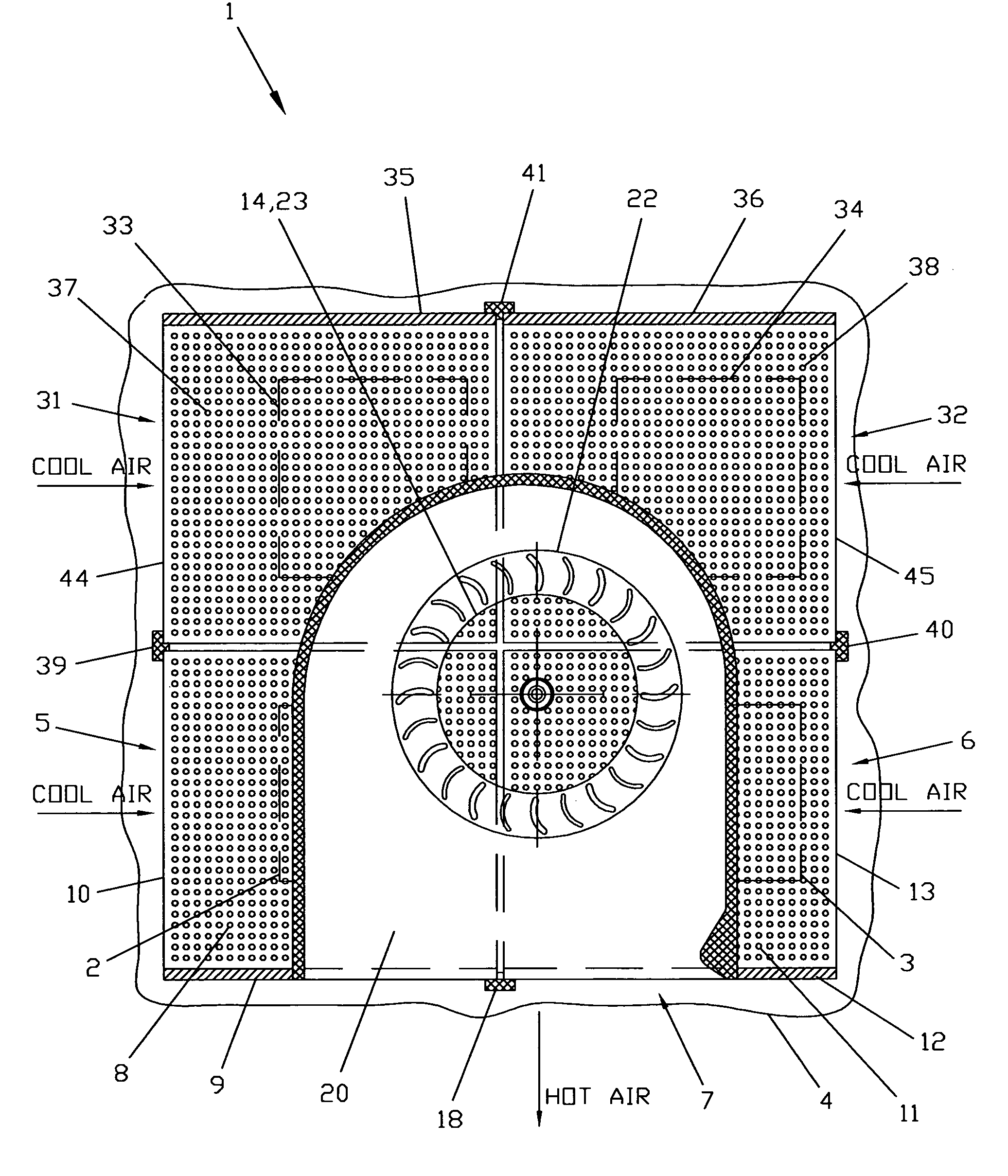
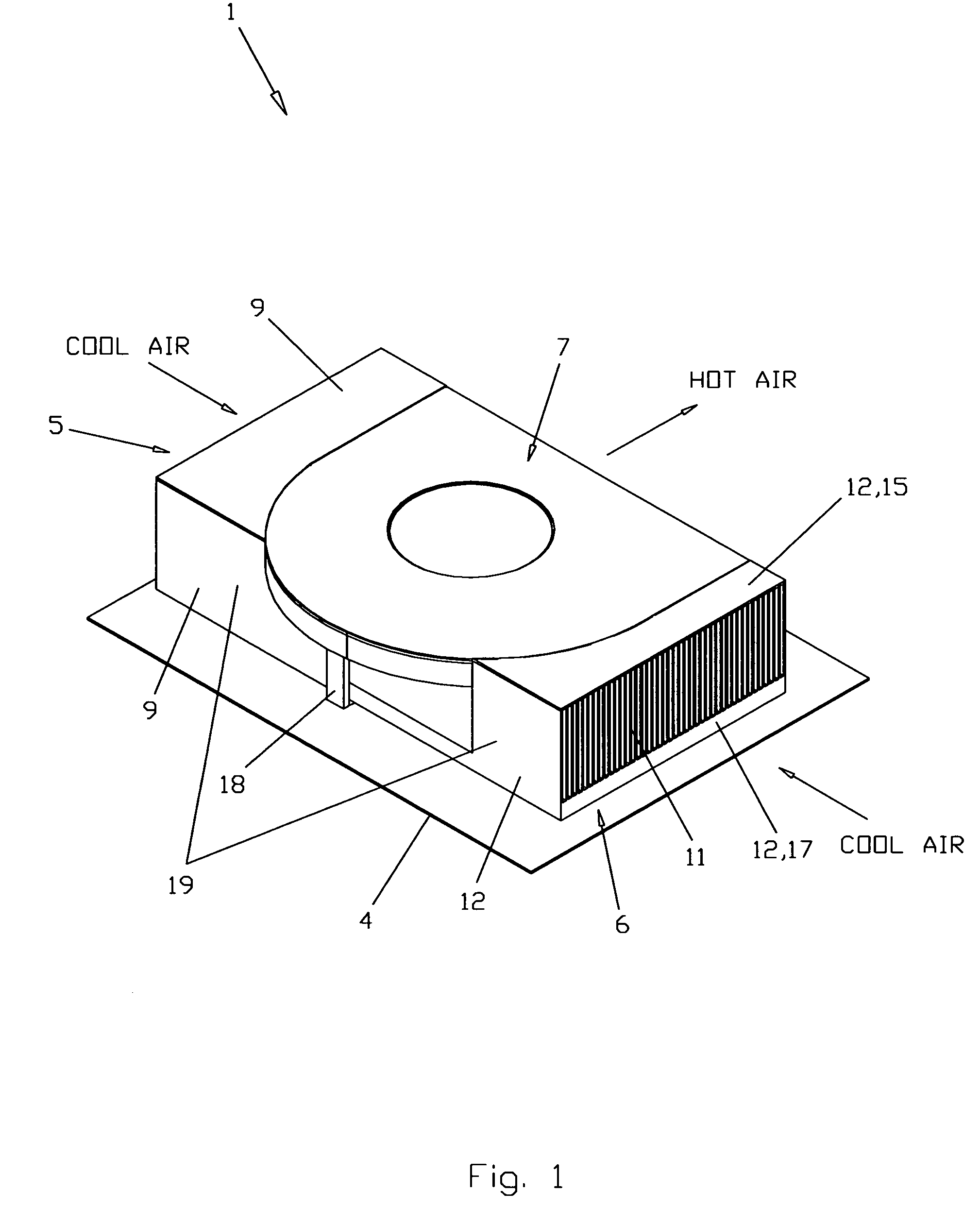
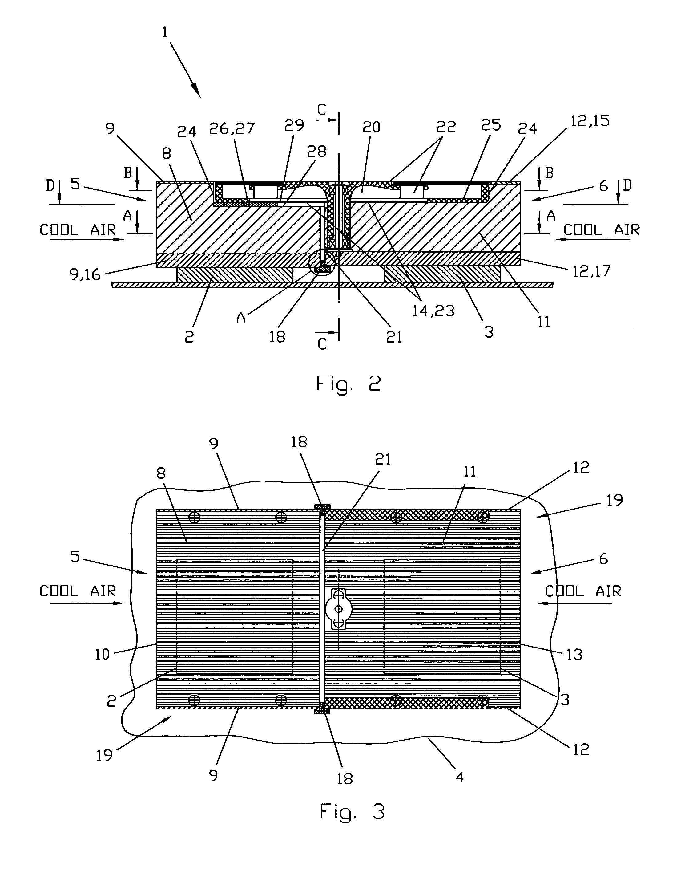
[0033]Claimed invention will be described in detail below with reference to the accompanying drawings on FIGS. 1–12.

[0034]In the first embodiment (FIGS. 1–6) a multi-heatsink integrated cooler 1 for direct cooling of two electronic components 2 and 3 located on a common horizontal board 4 comprises two heatsinks 5 and 6 and one common radial blower 7. The heatsink 5 comprises heat-exchanging means 8 and a housing 9 with an inflow opening 10. The heatsink 6 comprises heat-exchanging means 11 and a housing 12 with an inflow opening 13 and an outflow opening 14 located in the upper part 15 of the housing 12. The heat-exchanging means 8 and 11 are made as fins. Each of said heatsinks 5 and 6 is located independently in tight contact with one of said electronic components 2 and 3,—the heatsink 5 on the electronic component 2 and the heatsink 6 on the electronic component 3, so the lower part (providing thermal contact base) 16 of the housing 9 of the heatsink 5 is in tight contact with t...


PUM


Abstract

A multi-heatsink integrated cooler for direct cooling of at least two electronic components comprises at least two heatsinks with heat-exchanging means and housings with inflow and outflow openings and one common blower. Each of the heatsinks is located independently in tight contact with one of said electronic components. The housings of all said heatsinks are hydraulically connected in a common system of airflow between said heat-exchanging means of all the heatsinks and the inside space of said blower by at least one sealing element from the elastic material located in the clearance between nearest parts of said housings thus compensating the differences in locations and tolerances. The cooler comprises the radial blower located overlapping at least one of said heatsinks so that an inlet of said blower is coincided with the outflow opening of said common system of airflow. Said blower is located directly on the surface of one of said heatsinks overlapping at least one another heatsink.

Description

BACKGROUND OF THE INVENTION[0001]The present invention relates generally to cooling systems. More particularly, the present invention relates to the coolers for regulating the temperature of electronic devices. The present invention is particularly, but not exclusively, useful for cooling systems that regulate the temperature of electronic components of blade servers.[0002]The regulation of the temperature of electronic components like processors due to heat generated inside the housing of an electronic device like a blade server is an important consideration during the design of an electronic device. Cooling is important because if left unchecked, heat can cause electronic devices to malfunction during use or lead to premature device failure. As improvements in processor speed occur, the amount of heat generated by the faster processors also increases. Additionally, improved processors require larger power supplies and auxiliary components that generate increased amounts of heat an...

Claims


Application Information

Patent Timeline
Patent Type & Authority Patents(United States)
IPC IPC(8): F28F7/00H01L23/467H05K7/20
CPCH01L23/467H01L2924/0002H01L2924/00
Inventor LOPATINSKY, EDWARDSHOSTAK, NAUMFEDOSEYEV, LEV
Owner ROTYS
Why Eureka
Try Eureka