Rotatable and reversibly expandable spinal hydraulic prosthetic device

Inactive Publication Date: 2006-01-03
X PANTU FLEX DRD LIABILITY
View PDF39 Cites 185 Cited by
  • Summary
  • Abstract
  • Description
  • Claims
  • Application Information

AI Technical Summary

Benefits of technology

[0035]It is a further objective of the present spinal implant to provide an extension tubing which allows for post implantation intervertebral gap adjustments.
[0036]It is an additional objective of the present invention to provide a spinal prosthetic implant device which can be implanted in the space formerly occupied by the nucleus pulposus whereby the annulus fibrosus is left intact.
[0037]It is a further objective of the present spinal implant device to provide a system which can be substituted

Problems solved by technology

These devices generally permit a small amount of articulation between the vertebrae, but the functional and structural longevity of the elastomeric materials and their bonding agents are often quite short.
The device as taught is satisfactory for normal ambulatory loads but may under certain circumstances not provide sufficient means for safely accommodating higher than normal force loads.
The prosthetic device is neither rotatable between the vertebrae, nor does it provide for sufficient bending in the forward, backward or lateral directions.
This device permits only limited rotation and flexural freedom.
In addition, that device does not permit individualized adjustment of the intervertebral spacing as does the present invention.
The device does not allow for rotation between vertebrae, thus failing to give the user fully articulated movement.
The inflatable bag does not permit rotation between the vertebrae.
This system

Method used


Image

  • Rotatable and reversibly expandable spinal hydraulic prosthetic device
  • Rotatable and reversibly expandable spinal hydraulic prosthetic device
  • Rotatable and reversibly expandable spinal hydraulic prosthetic device

Examples


Embodiment Construction

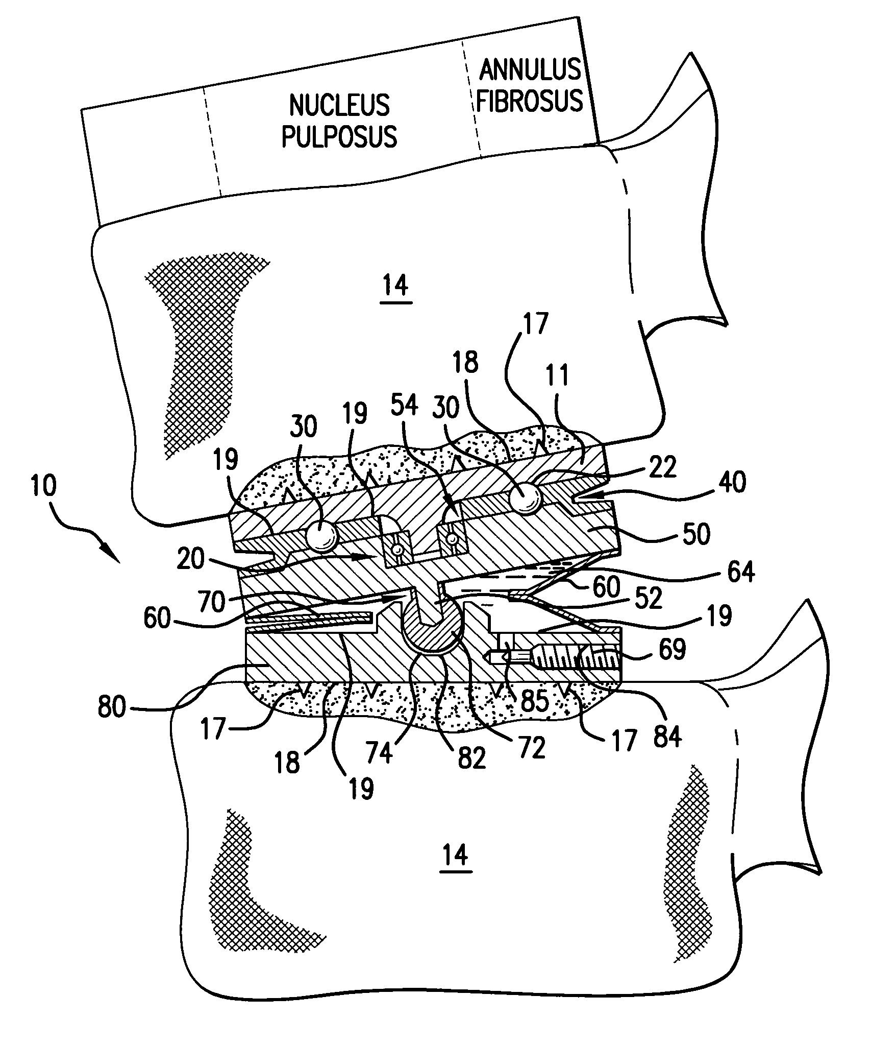
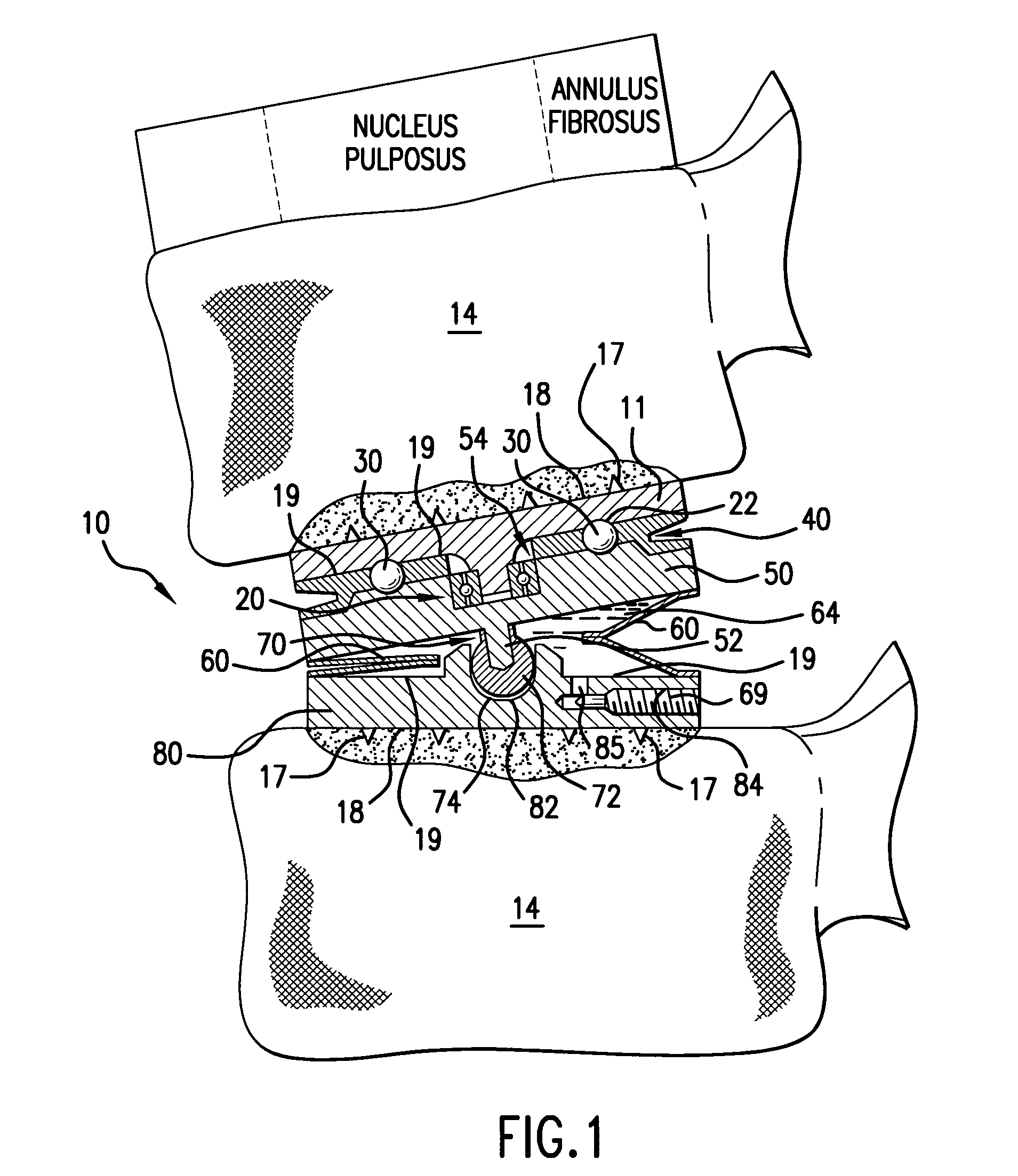
[0046]FIG. 1 illustrates the preferred embodiment of the spinal prosthetic device 10 implanted between two lumbar vertebrae 14. The preferred embodiment of the device with one bellows 60 is shown in FIG. 1 tilted to its maximum inclination, which may be adjustably varied. The prosthetic device 10 may be used to replace an entire diseased spinal intervertebral disc, or it may be positioned within the nucleus pulposus space of a spinal disc wherein the nucleus pulposus material has been removed. The device 10 is shown in FIG. 1 as it would be located if the annulus fibrosus were left intact. A larger version of this device configuration seen in FIGS. 1 and 4A may be similarly implanted within the space formerly occupied by the entire intervertebral disc, wherein both the nucleus pulposus and the annulus fibrosus are completely removed.

[0047]Referring now to FIG. 1, there is shown the rotatable and reversibly expandable spinal hydraulic prosthetic device 10. As shown in FIG. 1, the pro...


PUM

PropertyMeasurementUnit
Pressureaaaaaaaaaa
Electrical resistanceaaaaaaaaaa
Flexibilityaaaaaaaaaa

Abstract

An improved spinal intervertebral prosthetic device that offers all degrees of motion afforded by the anatomic spinal intervertebral disc, and by virtue of the incorporation of a dashpot assembly mechanism within reversibly displaceable bellows, provides hydraulic load bearing capability as well as limiting the maximum pressure that can be exerted on the bellows assembly by limiting the compression stroke of the device. The dashpot assembly also increases resistance to lateral shear loading in excess of the bellows convolutions acting alone. The spinal intervertebral prosthetic device absorbs varying axial loads via hydraulic pressure transfer to the bellows convolutions which can flex in a spring-like fashion. Rotational coupling of the upper crown plate and center bearings plate permits normal twisting movements, and spinal flexural freedom is provided by the bellows that are interposed between the center bearings plate and the lower crown plate.

Description

BACKGROUND OF THE INVENTIONField of the Invention[0001]The subject invention is directed to the field of prosthetic devices which may be surgically placed internal to the human or other mammalian body.[0002]The subject invention is directed in particular to spinal hydraulic prosthetic devices which may be implanted within a diseased spinal segment of the mammalian body in place of a nucleus pulposus or alternatively may be used to replace a diseased disc in totality.[0003]More particularly, the present invention relates to a rotatable as well as reversibly expandable spinal hydraulic prosthetic device for insertion within the vertebral column of a mammalian body.[0004]Still further, the subject invention directs itself to the field of a spinal disc prosthesis which incorporates some type of biocompatible metallic bellows being filled with a substantially incompressible fluid.[0005]Further, the subject invention relates to a spinal prosthesis having the ability to permit rotation bet...

Claims


Application Information

Patent Timeline
IPC IPC(8): A61F2/44A61B17/02A61F2/30A61F2/46
CPCA61F2/442A61F2/4611A61B2017/0256A61F2310/00317A61F2/30744A61F2/441A61F2002/30563A61F2002/30566A61F2002/30581A61F2002/30601A61F2002/30604A61F2002/3064A61F2002/30841A61F2002/4623A61F2002/4627A61F2002/4628A61F2310/00203A61F2/30742A61F2002/30639A61F2/4603
Inventor FLEISCHMANN, LEWIS W.GALUARDI, CHRISTOPHER
Owner X PANTU FLEX DRD LIABILITY
Why Eureka
Try Eureka