Photoelectric sensor with deflection angle adjustment arrangement

a technology of deflection angle and adjustment arrangement, which is applied in the field of photoelectric sensors, can solve the problems of inability to realize in terms of cost, difficulty in aligning the optical axis of a projected beam in the correct direction, and the deflection angle associated with the optical axis of a projected beam, etc., and achieve the effect of improving the degree of setting freedom

Inactive Publication Date: 2006-01-03
ORMON CORP
View PDF9 Cites 6 Cited by
  • Summary
  • Abstract
  • Description
  • Claims
  • Application Information

AI Technical Summary

Benefits of technology

[0008]The present invention has been made focusing attention on the problems described above and it is a general object of the present invention to improve a degree of setting freedom in various aspects related to a projected beam in a long distance type photoelectric sensor of this kind.

Problems solved by technology

Various problems have been traditionally pointed out in connection to setting of the projected beam.
A first problem is of an optical axis deflection angle associated with a projected beam.
Deflection angles of projected beams in actual products usually range from a good precision within ±2 degrees of a target optical axis to a poor precision within ±5 degrees of a target optical axis.
A cause for the presence of an optical axis deflection angle is an eccentricity of a light projecting lens relative to a light projecting element (a light source) and, in order to eliminate such a cause, it is required to raise precision requirements for constituent parts of a sensor head to extremities thereof, which cannot be realized in terms of cost.
In such circumstances, even with improvement on positioning precision between a sensor head case and a support member in installment of a sensor, difficulty remains in aligning the optical axis of a projected beam in a correct direction since the projected beam originally has an optical axis deflection angle in the sensor head itself.
Therefore, when mounting in an actual scene, a necessity arises for angular and positional adjustment mechanisms interposed between the sensor head case and the support member, raising problems of unfavorable cost performance and a cumbersome installment work.
Especially, since an optical axis adjustment tolerance in installment of a long distance type photoelectric sensor of this kind is narrow and delicate, it is considerably difficult to realize an angular adjustment mechanism capable of not only freely changing an angle but also fixing a state having adjusted in angle with certainty, and what's worse, in more of cases an inconvenience has been often encountered that optical, axis deviation occurs for the second time due to a clamping stress caused when being screwed in fixing despite of having completed angular adjustment at the expense of time and labor.
A second problem is that a different sensor product have had to be purchased for each case with different geometrical specifications (such as conversing light, diffusing light, slit light or the like) of a project beam so as to match with the geometrical specifications, though there are almost none of fundamental differences with respect to constituent parts in a sensor head case, which is not only a corresponding burden on the side of a user in terms of economy, but also inconveniences on the side of a maker of the sensors because of increase in the number of sensor products adversely affects a production cost and that accompanying complexity in product management leads to a higher production cost.

Method used


Image

  • Photoelectric sensor with deflection angle adjustment arrangement
  • Photoelectric sensor with deflection angle adjustment arrangement
  • Photoelectric sensor with deflection angle adjustment arrangement

Examples


Embodiment Construction

[0058]Detailed description will be given of preferred embodiments of the present invention below with reference to the accompanying drawings. Note that needless to say that the following embodiments are shown by way of illustration and example only and the spirit and scope of the present invention are to be defined based on the terms of the appended claims.

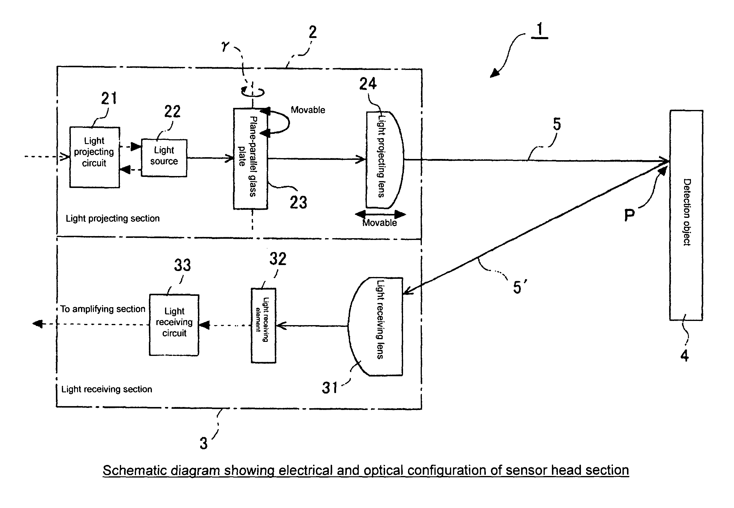
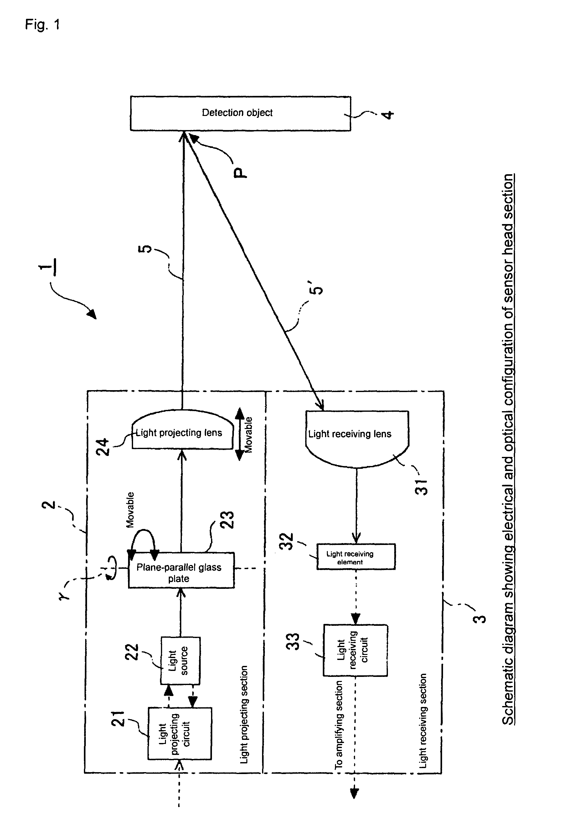
[0059]In FIG. 1, there is shown a schematic diagram showing an electrical and optical configuration of a sensor head section to which the present invention is applied. The photoelectric sensor, which is not shown in the figure, is an amplifier separation and diffuse reflection type photoelectric sensor constituted of a sensor head unit and an amplifier unit. In FIG. 1, there is shown main constituents in the sensor unit of the photoelectric sensor. That is, in the figure, a sensor head 1 includes: a light projecting section 2 and a light receiving section 3, both being integrated into a single piece. The light projecting section 2...


PUM


Abstract

A photoelectric sensor includes: a light projecting section projecting detection medium light to a detection object region; and a light receiving section receiving reflecting light or transmitted light from the detection object region, the sections being in a single piece or in separate pieces. The light projecting section includes: a light source generating the detection medium light; and a light projecting lens for collimating or collecting the detection medium light from the light source to form a beam spot or a light collecting point in the detection object region. The light projecting section further includes: a deflection angle adjusting unit capable of finely adjusting an optical axis deflection angle of the detection medium light projected to the detection object region from the light projecting section.

Description

BACKGROUND OF THE INVENTION[0001]1. Field of the Invention[0002]The present invention relates to a photoelectric sensor detecting an object by means of light projection and light reception and, more particularly, to a photoelectric sensor with an increased degree of optical setting freedom as to detection medium light (a projected beam) emitted from a light projection section.[0003]2. Description of the Related Art[0004]Disclosed in JP 2001-264453, A, for example, and others is a long distance type photoelectric sensor for detecting the presence or absence of an object in a production line or the like in a factory. Generally, a photoelectric sensor of this kind is of an amplifier separation type including a sensor head unit and an amplifier unit. As sensor head units, products of various types with different specifications have been available on the market, which are exemplified as follows: a minimum spot reflection type realizing a spot of 50 μm in diameter at a position of 70 mm±1...

Claims


Application Information

Patent Timeline
Patent Type & Authority Patents(United States)
IPC IPC(8): G06M7/00H01J40/14G01V8/14G01J1/02G01J1/04G01S7/48G01V8/12G02B7/00G02B7/02H01H35/00
CPCG01V8/12
Inventor OIKAWA, TAKAHIROSENGA, TADASHI
Owner ORMON CORP
Why Eureka
Try Eureka