Spectrophotometer, ellipsometer, polarimeter and the like systems

Inactive Publication Date: 2006-01-03
J A WOOLLAM CO
View PDF19 Cites 54 Cited by
  • Summary
  • Abstract
  • Description
  • Claims
  • Application Information

AI Technical Summary

Benefits of technology

[0114]i. a Berek-type Variable Retarder, the optical axis of which is oriented essentially perpendicular to the surface thereof, which Berek-type Retarder can be tilted about multiple axes to align said optical axis such that it is coincident with an incident polarized beam of light and thereby cause only a negligible attenuation effect, rather than a

Problems solved by technology

Many challenges faced development of (VUV) ellipsometer systems, including the fact that many optical element materials absorb in the (VUV) wavelength range.
Application problems have been identified with the design of the monochromator system as described, in that wiring and electronic components have to date been included inside the substantially enclosed space within the enclosure.
Outgassing from wiring and electronic components etc., (as required where Vacuum-Ultraviolet (VUV) wavelengths are utilized), can require very long periods of time.
Further, electrical connections to components such as the means for providing the first and second slits and rotating effecting means for the first and second stage which comprises thereupon a plurality of gratings, to date, have been hard wired thereto, thereby making repla

Method used


Image

  • Spectrophotometer, ellipsometer, polarimeter and the like systems
  • Spectrophotometer, ellipsometer, polarimeter and the like systems
  • Spectrophotometer, ellipsometer, polarimeter and the like systems

Examples


Embodiment Construction

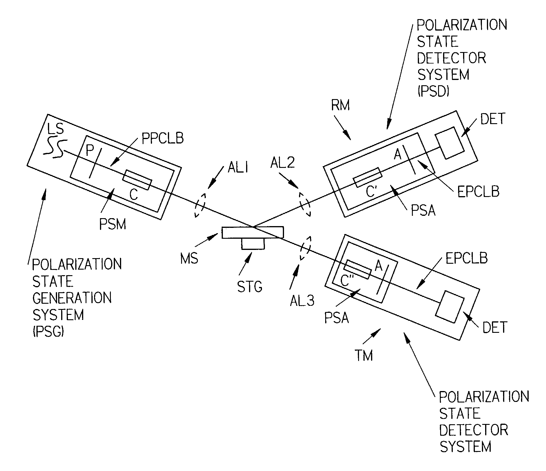
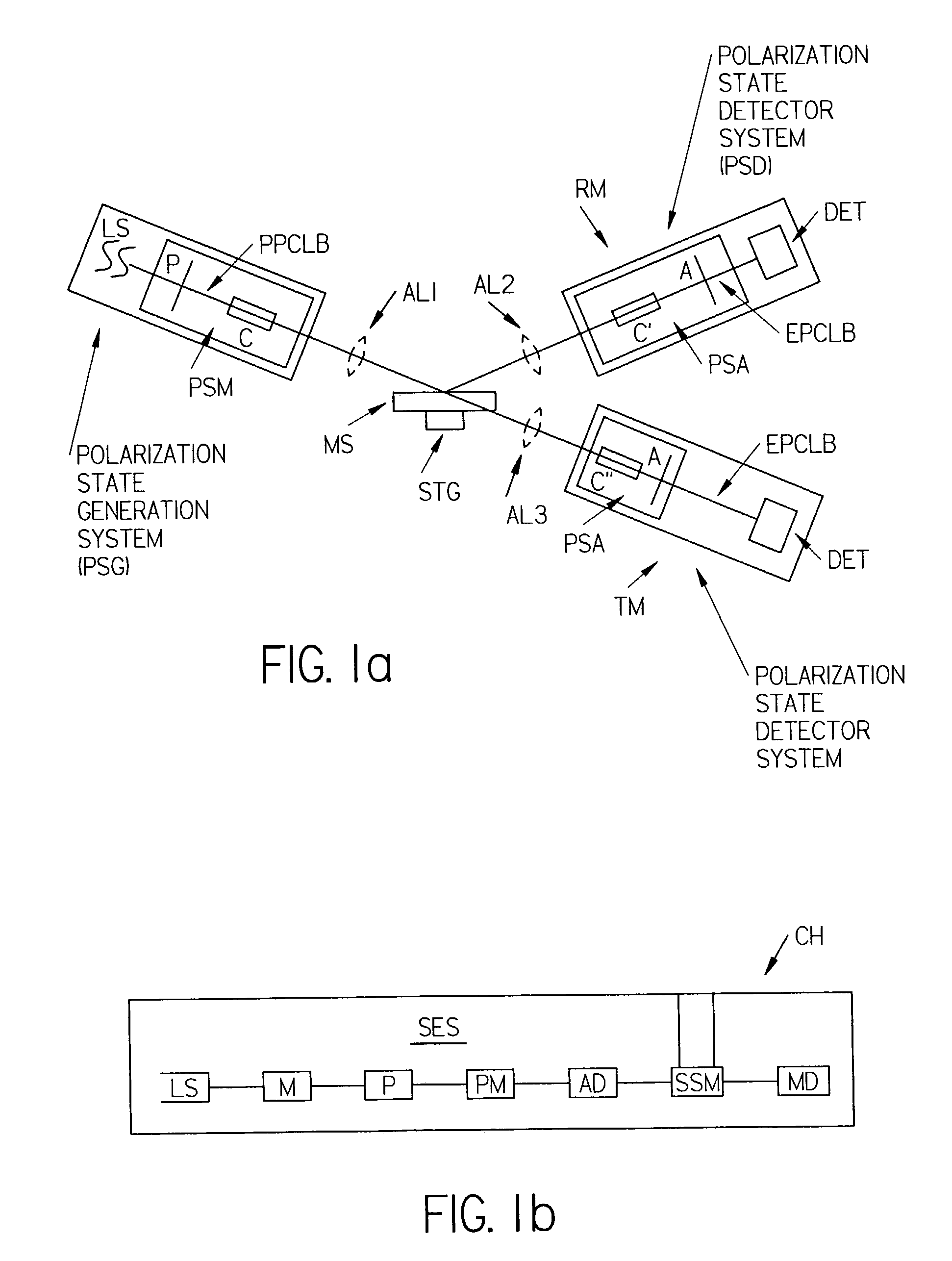
[0268]Turning to the Drawings, FIG. 1a shows a diagram of an ellipsometer / polarimeter system for use in both reflection (RF) and transmission (TM) modes. A source of monochromatic or polychromatic electromagnetic radiation (LS) is shown to, via polarization state modifier (PSM), which is demonstrated as being comprised of an Polarizer (P) and optionally a Compensator (C), provide a polarized beam of electromagnetic radiation (PPCLB) which is directed to interact with a material system (MS) which is placed on a stage (STG). (Note that conventional terminology identifies a Polarization State Generation System (PSG) as a combination of said source of monochromatic or polychromatic electromagnetic radiation (LS) and a Polarization State Modifier (PSM), which Polarization State Modifier (PSM) is demonstrated as being comprised of a Polarizer (P) and optionally a Compensator (C)). After interaction with the material system (MS), propagated electromagnetic beam (PPCLB) emerges as (EPCLB), ...


PUM


Abstract

Disclosed are improvements in ellipsometer and the like systems capable of operating in the Vacuum-Ultra-Violet (VUV) to Near Infrared (NIR) wavelength range, and methodology of use.

Description

[0001]This application is a Continuation-In-Part of Allowed application Ser. No. 09 / 531,877 Filed Mar. 21, 2000 now U.S. Pat. No. 6,535,286; and from Ser. No. 10 / 178,723 filed Jun. 24, 2002; and Ser. No. 09 / 583,229 filed May 30, 2000 now U.S. Pat. No. 6,804,004; and from Ser. No. 09 / 864,840 filed May 24, 2001 now U.S. Pat. No. 6,456,376; and Ser. No. 09 / 845,548 filed Apr. 30, 2001 now U.S. Pat. No. 6,585,128; and claims benefit of Provisional Application Ser. Nos. 60 / 300,714 filed Jun. 26, 2001, and 60 / 424,589 filed Nov. 7, 2002, and 60 / 427,043 filed Nov. 18, 2002 and 60 / 431,489 filed Dec. 6, 2002.TECHNICAL FIELD[0002]The disclosed invention relates to the use of electromagnetic radiation to monitor sample systems, and more particularly to improvements in ellipsometer and the like systems which are capable of operating in the Vacuum-Ultra-Violet (VUV) wavelength range as well as in the Visible and near Infrared (NIR) ranges, including methodology of use. Said improvements enable gre...

Claims


Application Information

Patent Timeline
IPC IPC(8): G01J4/00
CPCG01J3/02G01J3/0202G01J3/021G01J3/0235G01J3/0237G01J3/04G01J3/12G01J4/00G01N21/211G01J3/0291G01N2021/213
Inventor WOOLLAM, JOHN A.GREEN, STEVEN E.HE, PINGJOHS, BLAINE D.HERZINGER, CRAIG M.PFEIFFER, GALEN L.GUENTHER, BRIAN D.LIPHARDT, MARTIN M.
Owner J A WOOLLAM CO
Why Eureka
Try Eureka