Carriage arm assembly for magnetic disk drive

a technology of magnetic disk drive and arm assembly, which is applied in the direction of supporting heads, recording information storage, instruments, etc., can solve the problems of insufficient damage caused by viscoelastic materials, and achieve the effect of reducing the number of parts, improving workability, and increasing the thickness of the arms

Inactive Publication Date: 2006-01-03
HITACHI GLOBAL STORAGE TECH JAPAN LTD
View PDF4 Cites 9 Cited by
  • Summary
  • Abstract
  • Description
  • Claims
  • Application Information

AI Technical Summary

Benefits of technology

[0021]By providing a structure in which the restraint member having a surface opposing to inner side surfaces of the first arm portion and the second arm portion is placed between the first arm portion and the second arm portion, and in which the first arm portion and the second arm portion are coupled to each other via the viscoelastic materials, that is, by providing a structure in which the restraint member and the viscoelastic materials are fittingly accommodated in a hole portion of the arms, it is possible to obtain a damping structure without increasing thickness of the arms.
[0022]By providing a structure in which a long tail portion corresponding to a wiring portion for an electrical signal of a magnetic head is placed between the first arm portion and the second arm portion, and in which the long tail portion serves also as the restraint member, it is possible to reduce the number of parts.
[0023]By a structure in which respective arms are separate parts and in which the carriage arm assembly is configured by stacking a plurality of the arms, it is possible to assemble the carriage arm assembly after disposing a restraint member, a viscoelastic material and the like of each arm, so that workability can be substantially improved.
[0024]The structure includes the restraint member for each arm, which member is previously integrally formed, so that the number of parts can be reduced, and the number of working processes can be reduced.
[0025]By providing the restraint member with a hole portion on which the viscoelastic material is pressed, it is possible to achieve a structure having a good assembling ability.
[0026]A light material such as a resin may be used for the restraint member so that the weight of the entire carriage arm assembly is reduced, thereby it is possible to prevent the access time from being slower, prevent the servo band width from being narrower due to lowering of a main resonant frequency, and eliminate other inconveniences.

Problems solved by technology

Assuming that the restraint member is not fixed to the body and supported only by the first arm portion and the second arm portion, when the first arm portion and the second arm portion displace in the same out-plane direction, the first arm portion, the second arm portion, the restraint member, and the viscoelastic materials are integrally displaced so that the damping by the viscoelastic materials is insufficient.

Method used


Image

  • Carriage arm assembly for magnetic disk drive
  • Carriage arm assembly for magnetic disk drive
  • Carriage arm assembly for magnetic disk drive

Examples


first embodiment

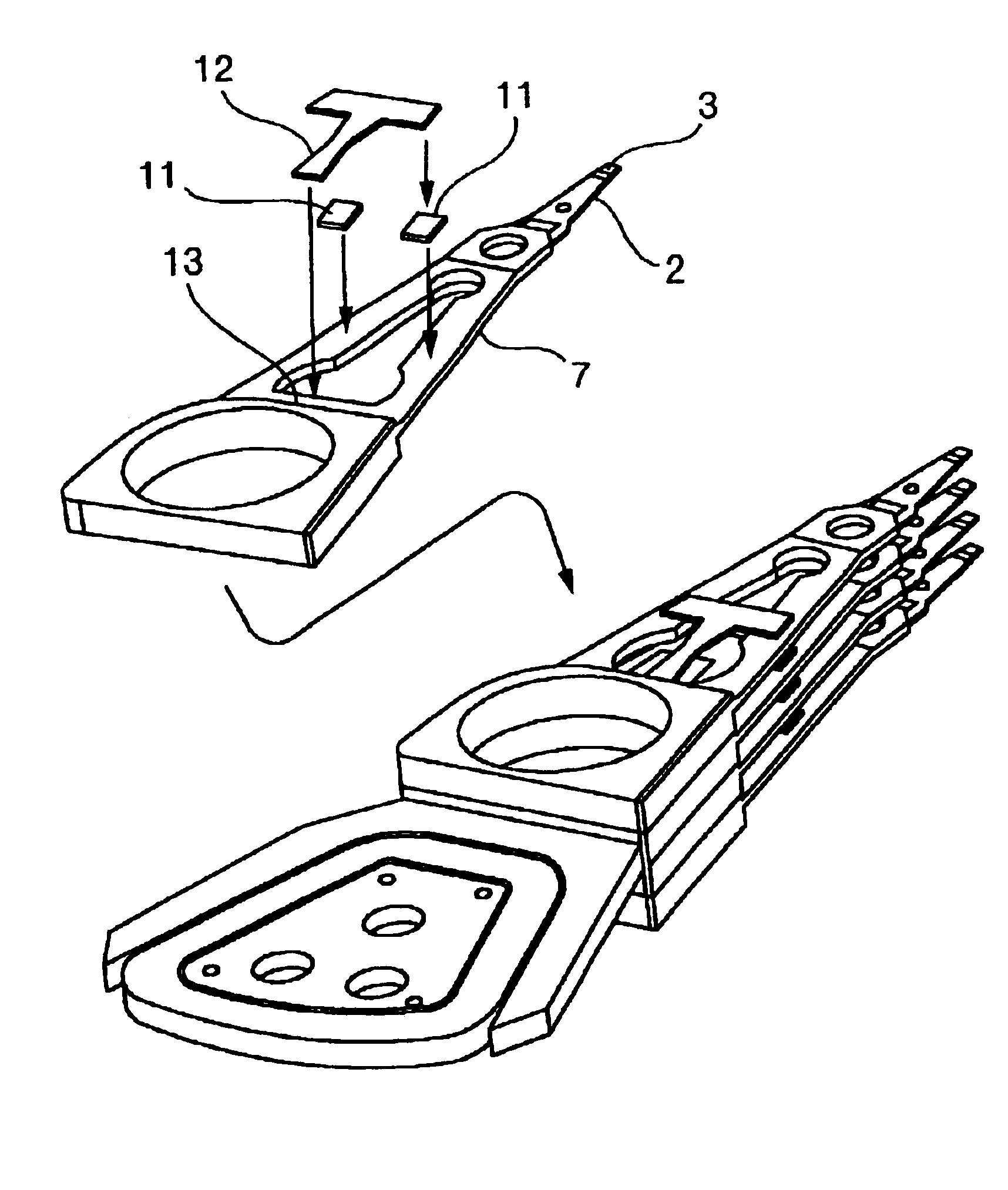
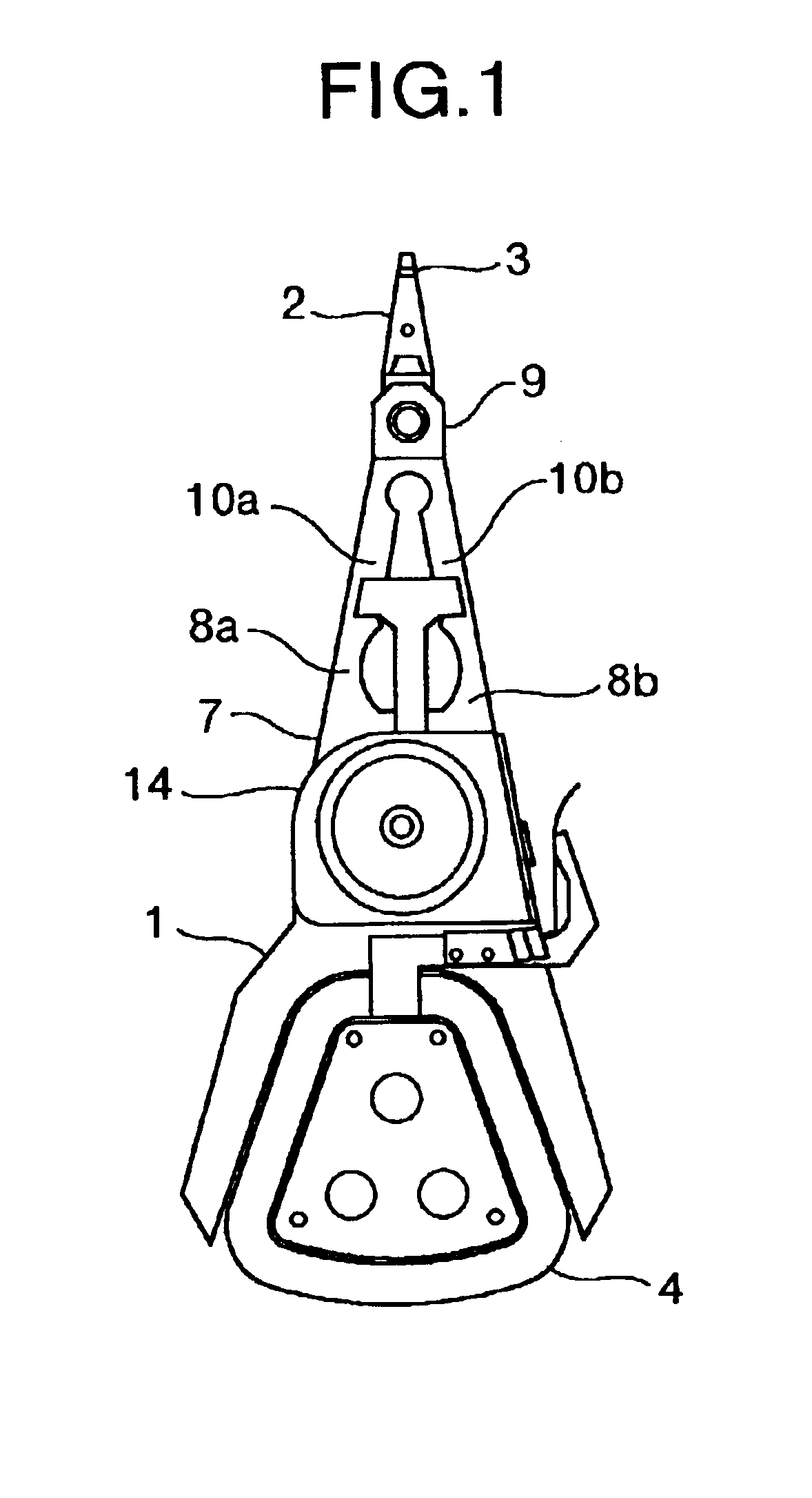
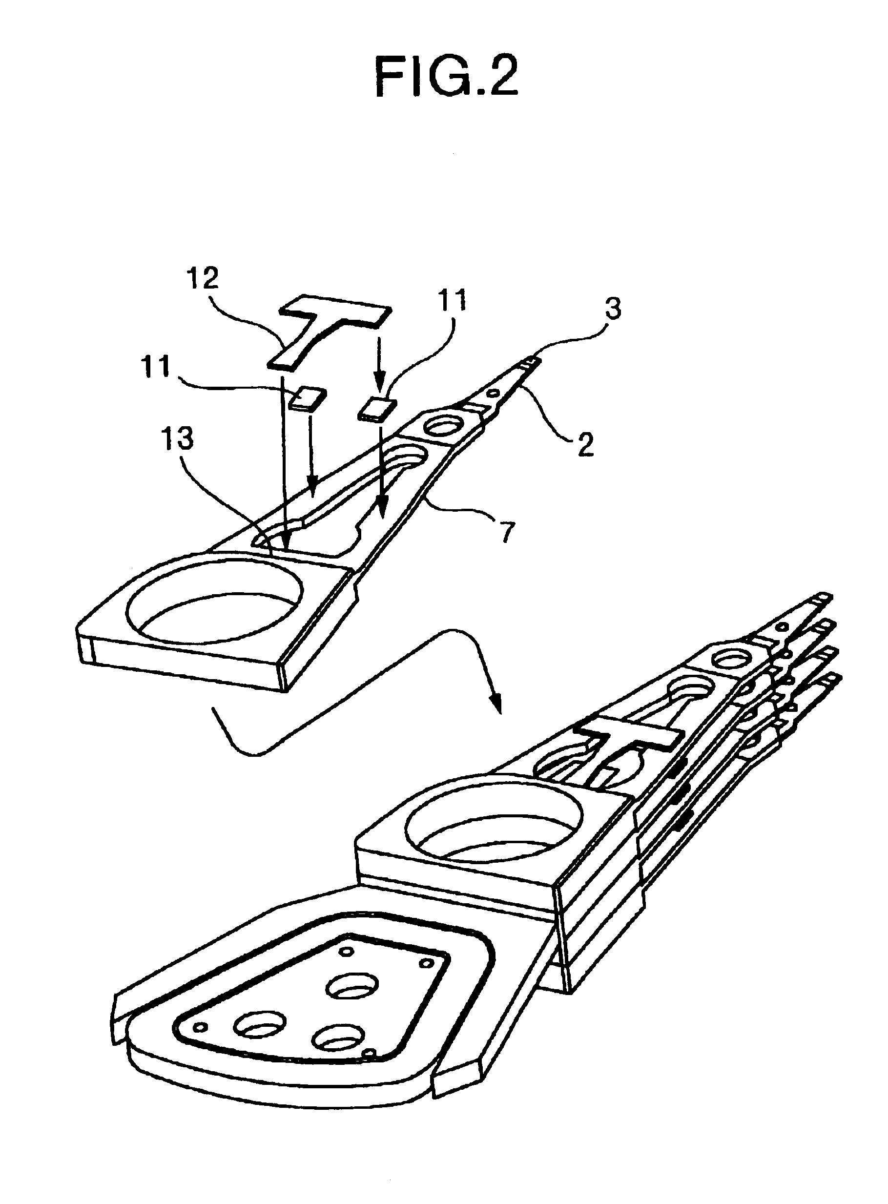
[0034]FIG. 1 is a top view of a carriage arm assembly to which the present invention is applied, and FIG. 2 is a perspective view illustrating a method of assembling the carriage arm assembly. In addition, an example of a magnetic disk drive equipped with the carriage arm assembly according to the present invention is shown in FIG. 3.

[0035]A slider 3 equipped with a magnetic head (not shown) is mounted at a tip end of the carriage arm assembly 1 via a suspension 2. By passing electric current through a coil 4, a force is generated between a voice coil motor 5 and the coil 4 so that the carriage arm assembly 1 can rotate about a bearing portion to position the slider 3 at any radial location on a disk 6.

[0036]A carriage arm 7 includes a first arm portion 8a and a second arm portion 8b, and a fixation portion 9 for the suspension. A T-shaped restraint board 12 is affixed through viscoelastic materials 11 to surfaces of arm center portions 10a and 10b parallel to a disk surface, so as...

second embodiment

[0039]FIG. 4 is a perspective view of a carriage arm assembly to which the present invention is applied, and FIG. 5 is a perspective view illustrating a method of assembling the carriage arm assembly.

[0040]Each carriage arm 7 is provided with a hole portion 17 which is surrounded by arm portions 8a and 8b, a fixation portion 9 for the suspension, and a body 14, and an arm damper main body 15 is placed in the hole portions 17 in an inscribed manner. A material of the arm damper main body 15 is a resin, and the arm damper main body 15 has a structure as shown in FIG. 5 in which restraint members of the arms are integrally formed and is adhesively fixed through an arm damper fixation portion 18 to the body 14. Further, in order to avoid interference with the rotating disk, a construction between the arms is configured as a constriction in which the disk is located, and the restraint member of each arm has the same thickness as that of the arm. The viscoelastic material 16 placed betwe...

third embodiment

[0047]FIG. 6 is a top view of a carriage arm assembly to which the present invention is applied. Each carriage arm 7 is provided with a hole portion 17 which is surrounded by the arm portions 8a and 8b, the fixation portion 9 for the suspension, and the body 14, and the arm damper member 21 made of resin is previously molded in the hole portions 17. Gaps having a width of 50 μm to 200 μm are provided between the arm damper member 21 and the arm portions 8a and 8b of the arms, and fluid viscoelastic material 22 is flowed into the gaps and stuck therein to fill in the gaps between the arm damper member 21 and the arm portions 8a and 8b. This enables substantial elimination of processes, such as a process of mounting the arm damper member, so that substantial reduction in the number of processes and parts is achieved.

[0048]By using a carriage arm assembly according to the first, second, or third embodiments of the present invention, a high damping effect can be provided in various vib...


PUM

PropertyMeasurementUnit
thicknessaaaaaaaaaa
frequencyaaaaaaaaaa
frequencyaaaaaaaaaa

Abstract

A magnetic disk drive having a high recording density and enabling high speed transfer is achieved by reducing vibration of a carriage arm assembly to reduce a positioning error. The disk drive is configured so that a carriage arm is configured by two arm portions, the arm portions being coupled to each other by a restraint member through a viscoelastic material, the restraint member being supported on a carriage body or an area of the carriage arm in the vicinity of the body by means of adhesion or a viscoelastic material. By providing a high damping effect against various vibration modes in which in-plane bending and out-plane bending of the carriage arm are generated, vibration of the carriage arm assembly is suppressed, so that the positioning error is reduced, thereby the magnetic disk drive having a high recording density can be achieved.

Description

CROSS-REFERENCES TO RELATED APPLICATIONS[0001]This application is a continuation-in-part of application Ser. No. 10 / 157,087 filed May 30, 2002 now U.S. Pat No. 6,879,467.BACKGROUND OF THE INVENTION[0002]1. Field of the Invention[0003]The present invention relates to a carriage arm assembly for a magnetic disk drive, in particular to a structure of a carriage arm assembly which is suitable for positioning a magnetic head.[0004]2. Description of the Prior Art[0005]Recently, in the field of a magnetic disk drive, it has been required to improve recording density in order to increase recording capacity. For this purpose, it is important to improve accuracy of positioning a magnetic head. However, as inhibition factors from improving the positioning accuracy, there are raised a positioning error due to vibration of a mechanism system resulting from rotation of a disk or from operation of positioning a carriage arm assembly, and a positioning error due to vibration added from the outside ...

Claims


Application Information

Patent Timeline
Patent Type & Authority Patents(United States)
IPC IPC(8): G11B5/55G11B5/48
CPCG11B5/4833G11B5/5582
Inventor NAGAHIRO, SHINSEGA, MASAHIKOARISAKA, TOSHIHIROSHIMIZU, TOSHIHIKOMASUDA, HIROMITSUHAMAGUCHI, TETSUYANAKAMURA, GENTAROATUMI, TAKENORI
Owner HITACHI GLOBAL STORAGE TECH JAPAN LTD
Why Eureka
Try Eureka