Exhaust valve mechanism in internal combustion engines

a technology of exhaust valve and internal combustion engine, which is applied in the direction of valve drives, machines/engines, output power, etc., can solve the problems of reducing the braking effect of the engine, increasing the braking height of the exhaust valve during the compression stroke, and limiting the valve play. , to achieve the effect of reducing the force and the contact pressure, reducing the contact pressure, and rapid upward or downward movemen

Inactive Publication Date: 2006-01-10
VOLVO LASTVAGNAR AB
View PDF6 Cites 36 Cited by
  • Summary
  • Abstract
  • Description
  • Claims
  • Application Information

AI Technical Summary

Benefits of technology

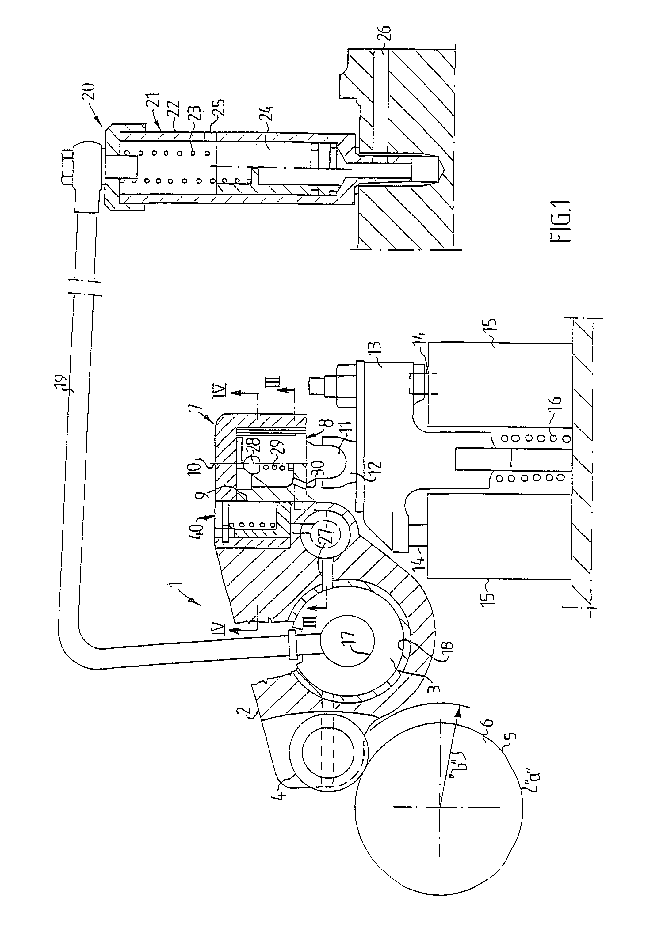
[0004]One purpose of the present invention is to achieve an exhaust valve mechanism of the type described by way of introduction which is constructed so that extra lifting of the exhaust valve during braking mode can be effected without affecting the regular lifting of the exhaust valve, to thereby avoid increasing the overlap between the exhaust valve and the intake valve with accompanying large back-flow and reduction of the mass-flow through the engine.
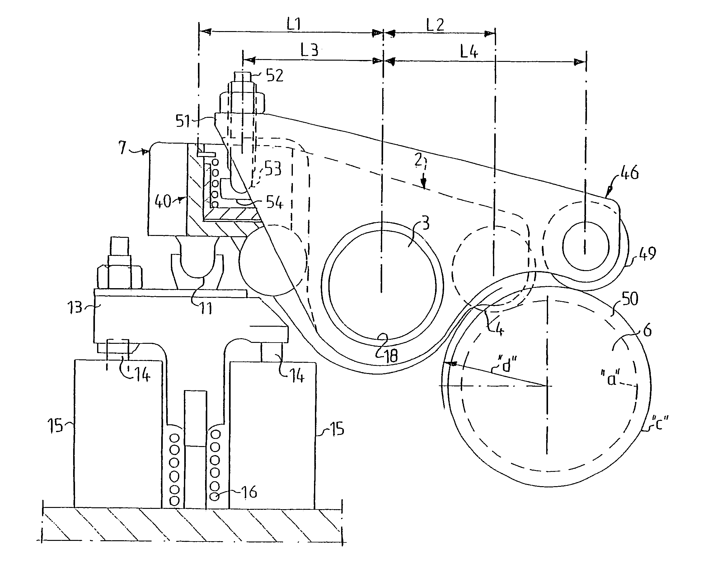
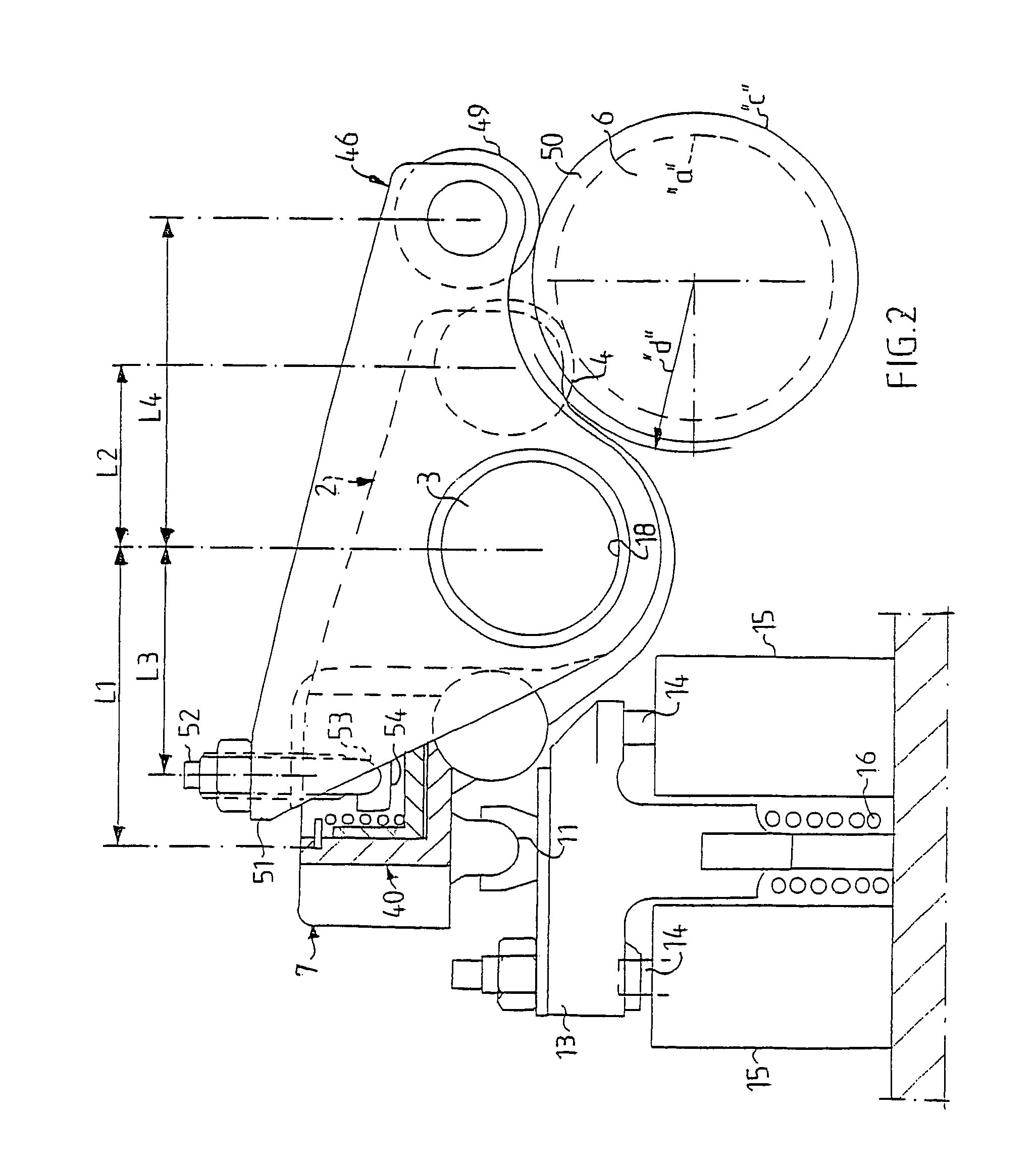
[0008]The invention is based on the idea of using two separate rocker arms, one for exhaust valve lifting during regular driving mode and one for exhaust valve lifting in braking mode. The regular exhaust rocker arm can have a normal lever ratio on the order of 1:1,4–1,6 and need only be dimensioned for the forces occurring during driving mode. The exhaust valve rocker arm for braking mode transmits the valve movement from a separate cam element, whereby the extra cam lobes on the cam elements for regular drive mode can be eliminated. The rocker arm for braking mode acts on the second piston which functions as a pump piston and pumps fluid to the first cylinder chamber. The pressure in the first cylinder chamber presses the first piston towards the exhaust valve. The valve movement during braking mode is thus transmitted partially hydraulically. The second exhaust rocker arm can have another lever ratio than the first exhaust rocker arm, e.g. 1:0,7–1,1, which reduces the forces and the contact pressure in the mechanism. The cam element cooperating with the second rocker arm can have a greater base diameter than the cam element of the first rocker arm, which reduces the contact pressure and / or offers more rapid upward or downward movement.
[0009]Through the invention it is possible to eliminate the large valve overlap which is necessary when extra cam lobes are used in the regulate cam element for braking mode, because a high and long ramp is not required to conceal the extra lobes during driving mode. The return flow of exhaust into the cylinder and on through the inlet port, caused by overpressure in the exhaust manifold, is thereby reduced.

Problems solved by technology

For example, an extra cam lobe can be placed in relation to the regular cam lobe so as to provide an extra exhaust valve lift during a later part of the compression stroke, resulting in a loss of a portion of the compression work during the compression stroke which will not be recovered during the expansion stroke.
This increases the braking effect of the engine.
In an engine with such an arrangement, the maximum lift height of the exhaust valve during the compression when engine braking, is limited to the valve play.
Since the pressure in the exhaust manifold is much higher than the pressure in the intake manifold in braking mode (ca 5 bar on the exhaust side as opposed to ca 1 bar on the intake side), hot exhaust in an amount depending on the overlap will flow between the exhaust side and the intake side during braking mode, which will impair the engine cooling during braking mode as compared to driving mode, especially since fuel as a cooling medium for the injection nozzle is not available during braking mode.

Method used


Image

  • Exhaust valve mechanism in internal combustion engines
  • Exhaust valve mechanism in internal combustion engines
  • Exhaust valve mechanism in internal combustion engines

Examples


Embodiment Construction

[0018]FIG. 1 shows schematically a valve mechanism 1 in an internal combustion engine (not shown). The mechanism 1 comprises an exhaust valve rocker arm 2, which is rockably mounted on a rocker arm shaft 3. One end of the rocker arm 2 has a cam follower roller 4, rotatably mounted thereon. The cam follower roller 4 is in contact with a schematically shown cam element 5 on the camshaft 6. The designation “a” indicates the base circle of the cam element 5, and “b” designates its top radius. At its end 7 opposite to the end with the cam follower roller 4, the rocker arm 2 is provided with a piston cylinder device 8 consisting of a cylinder chamber 9 formed in the rocker arm end 7 and a piston 10 housed in the cylinder chamber. The piston 10 is provided with a piston pin 11 with a spherical end extending into a socket 12 on a yoke 13 which, during operation, applies pressure to two exhaust valve spindles 14. 15 designates two valve springs for closing the valves. Beyond the springs 15 t...


PUM


Abstract

Valve mechanism in an internal combustion engine, includes a valve play-take up mechanism in the form of a piston in a cylinder chamber at one end of an exhaust rocker arm, and a hydraulic circuit with valve elements for supplying or draining off pressure fluid to and from the cylinder chamber. A second cylinder chamber with a piston acting in an opposite direction is arranged in the rocker arm and communicates with the first-mentioned cylinder chamber. A brake rocker arm is mounted on the same rocker arm shaft as the exhaust rocker arm and has an outer end, which acts against the piston in the second cylinder chamber. The brake rocker arm has its own cam element with brake cam lobes to one side of the exhaust rocker arm cam element.

Description

FIELD OF THE INVENTION[0001]An exhaust valve mechanism in an internal combustion engine, comprising at least one exhaust valve in each cylinder, a rocker arm shaft-mounted rocker arm for each cylinder for operating the exhaust valve, a cam shaft with a cam element for each rocker arm, said cam element cooperating with motion transmitting means at one end of the rocker arm, a first piston-cylinder device disposed between an opposite end of the rocker arm and the exhaust valve, said first piston-cylinder device having a first cylinder chamber in said opposite rocker arm end, a hydraulic circuit for supplying and draining off pressure fluid to and from said cylinder chamber, and a piston disposed in said cylinder chamber, said piston being biased towards the exhaust valve when pressure fluid is supplied to the cylinder chamber.BACKROUND OF THE INVENTION[0002]SE-A-468 132 describes an exhaust valve mechanism of the above mentioned type which, together with a special type of camshaft wit...

Claims


Application Information

Patent Timeline
Patent Type & Authority Patents(United States)
IPC IPC(8): F01L13/06F02D13/04F01L1/18
CPCF01L13/06F01L13/065F01L1/181F02D13/04F01L1/08F01L2760/004F01L2105/00F01L2305/00
Inventor PERSSON, PER
Owner VOLVO LASTVAGNAR AB
Why Eureka
Try Eureka