The presence of exhaust emissions may be detrimental to the health and well-being of persons who work in facilities in which such emissions are present.
Not only may these emissions be harmful to the long-term health or well-being of persons inside the facility, but these emissions are also unpleasant or repellent to the senses.
Furthermore, over time, the emissions may also
stain the interior surfaces of the facility, causing the building to become an unattractive, malodorous, or unpleasant work environment.
However, even though a variety of devices have been introduced into the marketplace, substantial problems with existing devices remain unresolved.
A significant problem with existing pressure differential distribution devices may be that they are large or take up a lot of space.
The
large size of current devices also presents a problem for installers.
If installed prior to other mechanical or electrical fixtures, a large pressure differential distribution device may present an obstacle to the installation of subsequent mechanical or electrical fixtures; on the other hand, if the emission extraction
system is to be installed after other fixtures are in place, a large
system may not fit as easily as a smaller one.
Additionally, large devices increase shipping costs inherent in transporting a heavier item.
Similarly, other types of large pressure differential distribution devices such as boom arms may furnish the
consumer with the ability to swing the pressure differential distribution device along an arc, providing some mobility, however, these devices generate an operating boundary within which other objects or equipment may not typically be used.
Another significant problem with existing pressure differential distribution devices may be that the various components of the device, even when in the stored position, are visually or mechanically exposed.
With respect to the mechanical
exposure of the device, having the components open to various types of physical mistreatment (for example, being inadvertently hit or run into) or to other environmental abuses (for example, chemical spills or spatters, or abrasives from various procedures) may lead to premature wear of the components.
With respect to the
visual appearance, not only may the components of the device lack pleasing aesthetics for the
consumer who may purchase the device (or not if the appearance is too awkward), but also to the public to which the device may connote an unattractive image.
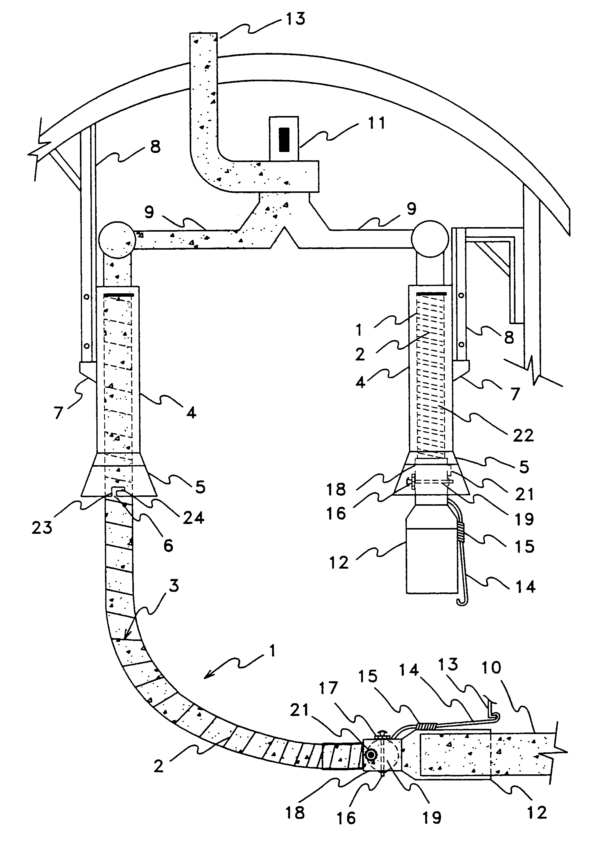
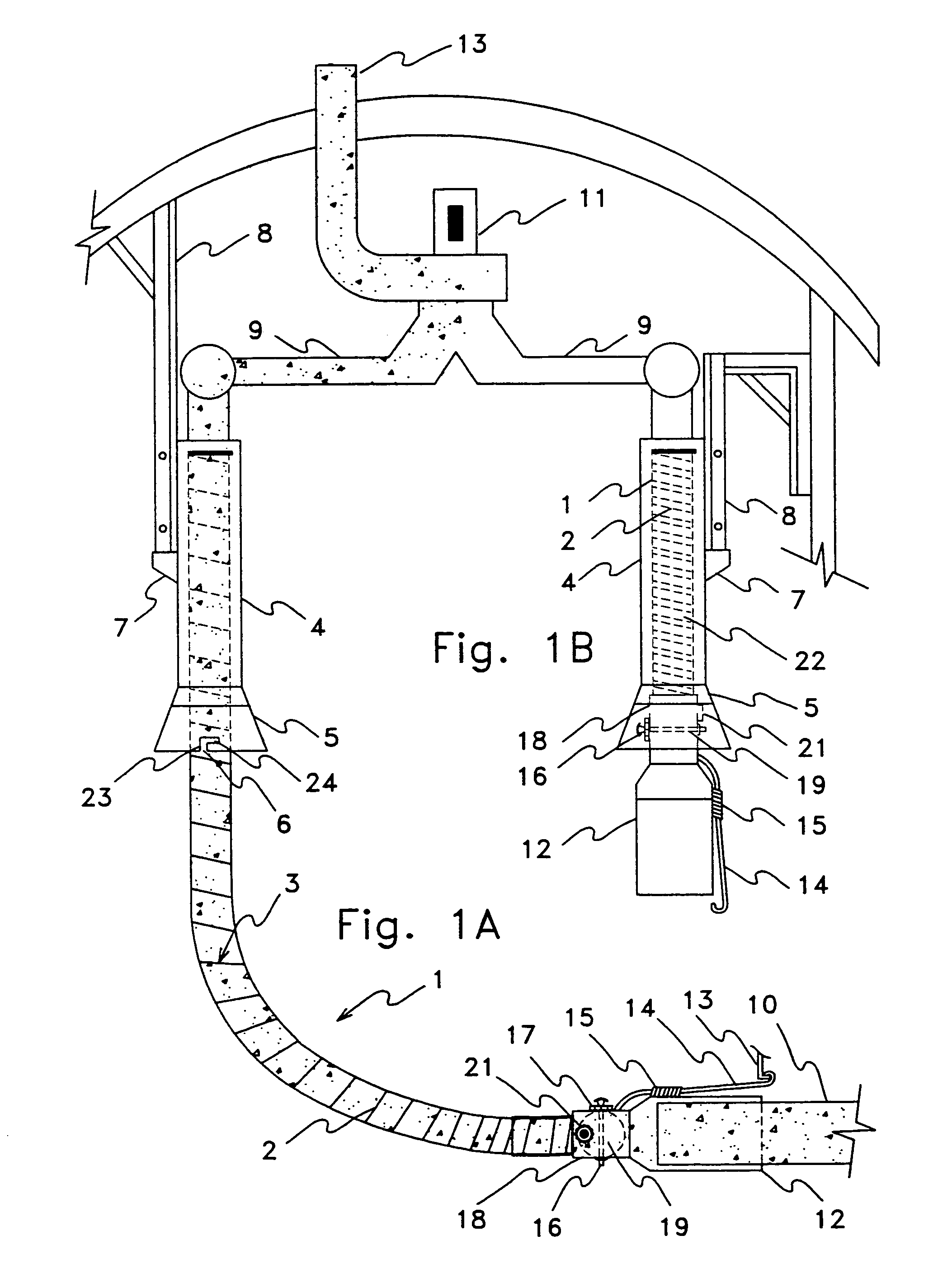
Another significant problem with existing pressure differential distribution devices may be that they utilize an exhaust hose that features a corrugated configuration.
This corrugation greatly diminishes the pressure differential generator's or exhaust fan's capacity to draw substances or emissions through the corrugated hose.
Unfortunately, as the power of the pressure differential generator increases, it becomes more expensive to purchase and to operate.
Moreover, a more powerful pressure differential generator may produce a greater amount of
noise, yet another irritant to those who are in close proximity to the
system.
Another significant problem with existing pressure differential distribution devices may be that certain hose retraction methods
pose risk of injury to persons.
If the hose is released prematurely by the operator, the hose or adapter may sling toward an unsuspecting fellow worker, or may cause damage to any object in its trajectory, due to the fact that the hoisting mechanism may be under high-torque spring tension.
This
hazard is particularly serious when the adapter is constructed of
metal or has protruding elements.
1–2, hereby incorporated by reference, improper use of a balancer mechanism “could result in serious injury, death, or property damage”.
Another significant problem with existing pressure differential distribution devices may be that they are difficult to operate.
Often existing devices have unwieldy product-to-operator interfaces which can be frustrating or annoying to the operator.
Many presently offered hoses or adapters, the components of the devices which are most frequently handled by the operator, are not designed to promote ease of use.
For example, high temperature hose, utilized in most military and governmental vehicle maintenance shops, historically has been made of heavy stainless steel or galvanized tubing that may be cumbersome or difficult to maneuver.
It is not uncommon for the operator, frustrated with the awkwardness or clumsiness of such hoses, to abandon their use even when abandonment may result in the waste of the financial resources invested in the pressure differential distribution device, or in the possibility of adverse health ramifications.
Another significant problem with existing pressure differential distribution devices may be that they do not accommodate applications in which the emission extraction system must be mobile.
In-floor devices are completely immobile and, once again, the length of the exhaust hose may be the limit of the area in which an in-floor system may be used.
Another significant problem with existing pressure differential distribution devices may be that they must be mounted with great precision or with significant structural attachment considerations, due to the larger weight of the devices.
Another significant problem with existing pressure differential distribution devices may be that the hoses hang in the way of persons.
Serpentine-type devices may provide better coverage than a hose reel type device or in-floor systems, but they can be unattractive and intrusive within the facility, because their hose frequently hangs in the way of the workers.
Another significant problem with existing pressure differential distribution devices may be that the exterior surfaces become hot.
High temperature stainless steel or galvanized hose can be prone to becoming dangerously hot when the system moves hot substances, such as emissions from vehicles.
Many of the existing adapters that attach to substance or emission sources may likewise be constructed of
metal and thus present the same possibility of inflicting injury.
Another significant problem with existing pressure differential distribution devices which are of the in-
floor type may be that they do not completely retract into the floor receptacle or the floor covers may be left open.
Persons working around such in-floor devices or open floor receptacles may suffer injury by
tripping, or stumbling over strewn components of the emission extraction system, or suffer injury by falling into the open receptacle into which the hose enters.
Moreover, the hose outlet
assembly, even when operating properly with the floor receptacle closed, may often protrude above the floor surface, presenting similar
hazard for those persons working around the device.
Another significant problem with existing pressure differential distribution devices may be that many components have hardened, protruding edges or corners or the like which can
cause injury to persons.
Another significant problem with existing pressure differential distribution devices may be that the hands of the operator may be injured if they are caught in the clamping mechanisms.
Yet another problem with existing pressure differential distribution devices may be that when multiple pressure differential distribution devices are connected to a common exhaust fan all draw or expel even when only one device may be in operation.
Since many existing devices or the terminal adaptors on such devices are not equipped with a
damper or closure, those devices not attached to a source of the substance to be moved will instead draw in the
ambient air within the facility and move it external to the facility, or may alternately move air from external to the facility and expel it into the facility.
This situation may be problematic because users of a facility may spend larger sums of money to heat or cool the
ambient air within their facility.
Still another problem with existing pressure differential distribution devices may be that existing terminal interfaces are constructed of
metal which may scratch, dent, or otherwise damage the equipment to which they are attached.
Another significant problem with existing pressure differential distribution devices may be premature hose failure due to high temperatures on the hose about the point of attachment to the substance or emission source.
This problem can be exacerbated by restrictions that may develop in the hose at the point where it is attached to the emission port, due to the
bend radius that may be required for attachment.
When the hose is continually restricted, hot spots may develop on the hose which may shorten the life of the hose.
Another problem with existing pressure differential distribution devices may be that the retraction device is complicated.
This level of complexity to retract a hose, or similar component, can be understood to be problematic both with regard to potential malfunctioning of the device and with regard to maintenance of the device.
Another significant problem with existing pressure differential distribution devices may be that the devices are undifferentiated and repetitive, showing numerous incarnations of a few basic concepts and ideas, many of which have been scarcely improved since their introduction.
As can be understood from the preceding
list of problems and the associated body of disclosed information, that many of the above-mentioned industries that use pressure differential distribution technology have experienced long felt but unresolved needs for improved apparatus and methods.
At the present time, pressure differential distribution technology suffers from a dearth of innovative ideas and methods; rather than attempting to create improved and imaginative concepts, the various industries continue to simply rely upon a few basic designs.
Although some of these apparatus and methods have existed for decades, all of the above mentioned problems within the emission extraction industry remain.
Some of these problems have never been addressed while other have been inadequately addressed.

