Intermediate transfer recording medium, print, and method for image formation thereby

a technology of image formation and recording medium, applied in the field of intermediate transfer recording medium, can solve the problems of reducing quality, increasing opaqueness, deteriorating transparency, etc., and achieve the effect of preventing deterioration of performance upon post-treatment of that portion, increasing opaqueness, and deteriorating transparency

Inactive Publication Date: 2006-01-10
DAI NIPPON PRINTING CO LTD
View PDF2 Cites 32 Cited by
  • Summary
  • Abstract
  • Description
  • Claims
  • Application Information

AI Technical Summary

Benefits of technology

[0012]According to the present invention, there is provided a print with an image formed thereon using an intermediate transfer recording medium, the intermediate transfer recording medium comprising a substrate film and a transfer portion, said transfer portion comprising at least a receptive layer, said transfer portion having been provided separably on the substrate film, said print having, on its at least one side, a portion on which the transfer portion has not been retransferred. According to this construction, in the intermediate transfer recording medium in its transfer portion, a portion free from the transfer portion (a void portion) is provided at a position corresponding to a sign panel, an IC chip, or a magnetic stripe portion in the print, or a design portion, such as a logo or a hologram, which has been previously printed on the object. The portion except for the void portion is retransferred onto the object to produce a print. When the transfer portion-non-retransferred portion is for a sign panel, an IC chip, a magnetic stripe or the like, a deterioration in performance upon the post treatment of that portion can be prevented. On the other hand, in the portion of a design, such as a logo or a hologram, the transfer of the transfer portion deteriorates the transparency (increases the opaqueness), leading to lowered quality. For this reason, the above means for solving the problem has been provided.

Problems solved by technology

On the other hand, in the portion of a design, such as a logo or a hologram, the transfer of the transfer portion deteriorates the transparency (increases the opaqueness), leading to lowered quality.

Method used


Image

  • Intermediate transfer recording medium, print, and method for image formation thereby
  • Intermediate transfer recording medium, print, and method for image formation thereby
  • Intermediate transfer recording medium, print, and method for image formation thereby

Examples


example a1

[0125]A 12 μm-thick transparent polyethylene terephthalate film was first provided as a substrate film. The following coating liquid for a stripping layer was coated on the surface of the substrate film, and the coating was dried to form a stripping layer at a coverage of 2.0 g / m2 on a dry basis on the whole area of the substrate film. In the following description, “parts” or “%” is by weight unless otherwise specified.

[0126]

(Coating liquid for stripping layer)Acrylic resin (BR-83, manufactured88partsby Mitsubishi Rayon Co., Ltd.)Polyester resin1partPolyethylene wax11partsMethyl ethyl ketone50partsToluene50parts

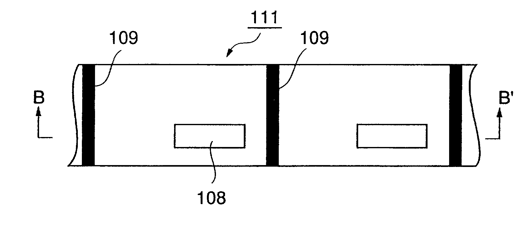
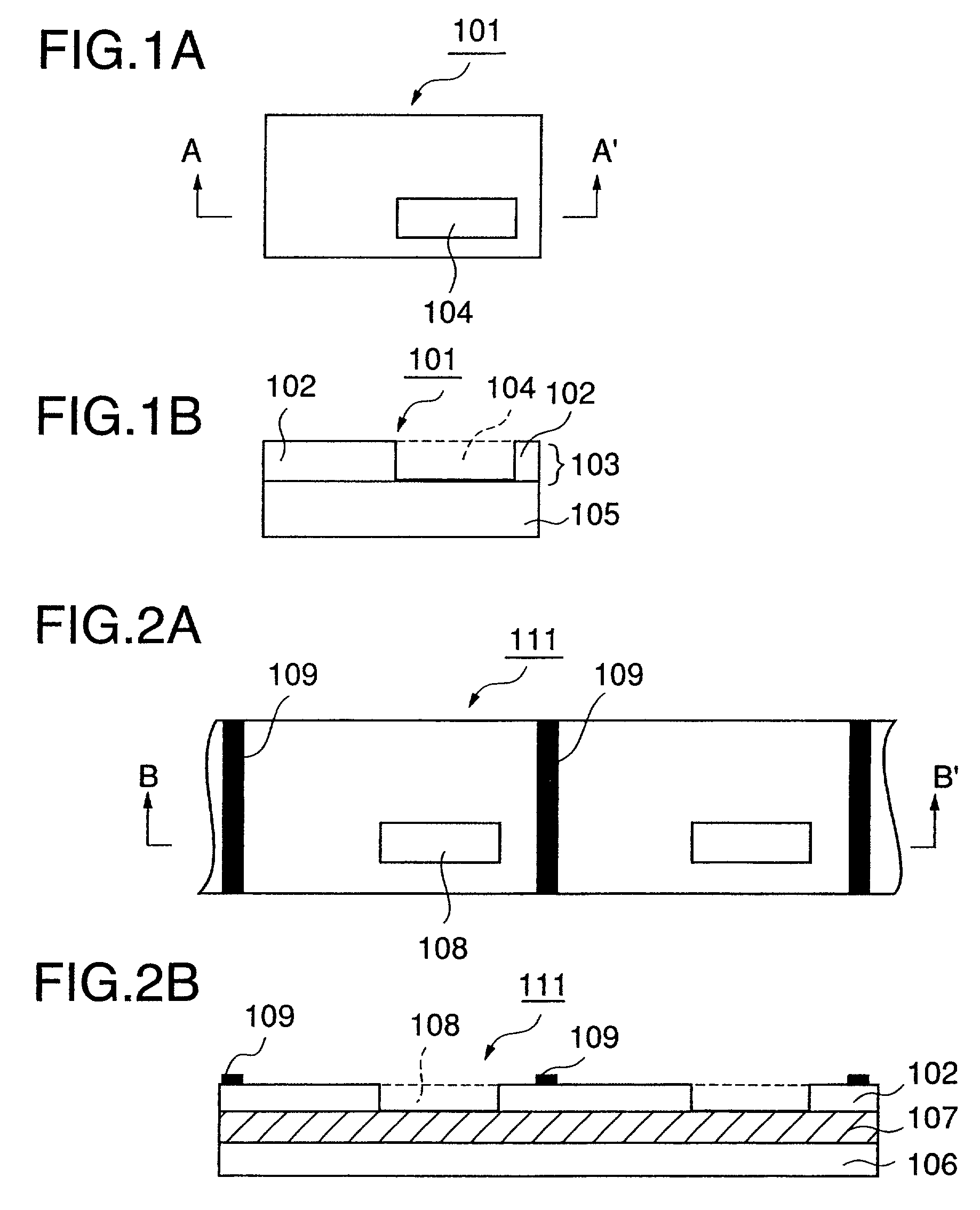
[0127]Next, the following coating liquid for a receptive layer was coated in a pattern shown in FIGS. 1 and 2 onto the stripping layer, and the coating was dried to form a receptive layer pattern at a coverage of 2.0 g / m2 on a dry basis (a transfer portion 103 having a void portion 108).

[0128]

(Coating liquid for receptive layer)Vinyl chloride-vinyl acetate copolymer40partsAcr...

example a2

[0131]The same substrate film as used in Example A1 was provided. The same coating liquid for a stripping layer as used in Example A1 was coated onto the surface of the substrate film, and the coating was dried to form a stripping layer at a coverage of 2.0 g / m2 on a dry basis on the whole area of the substrate film.

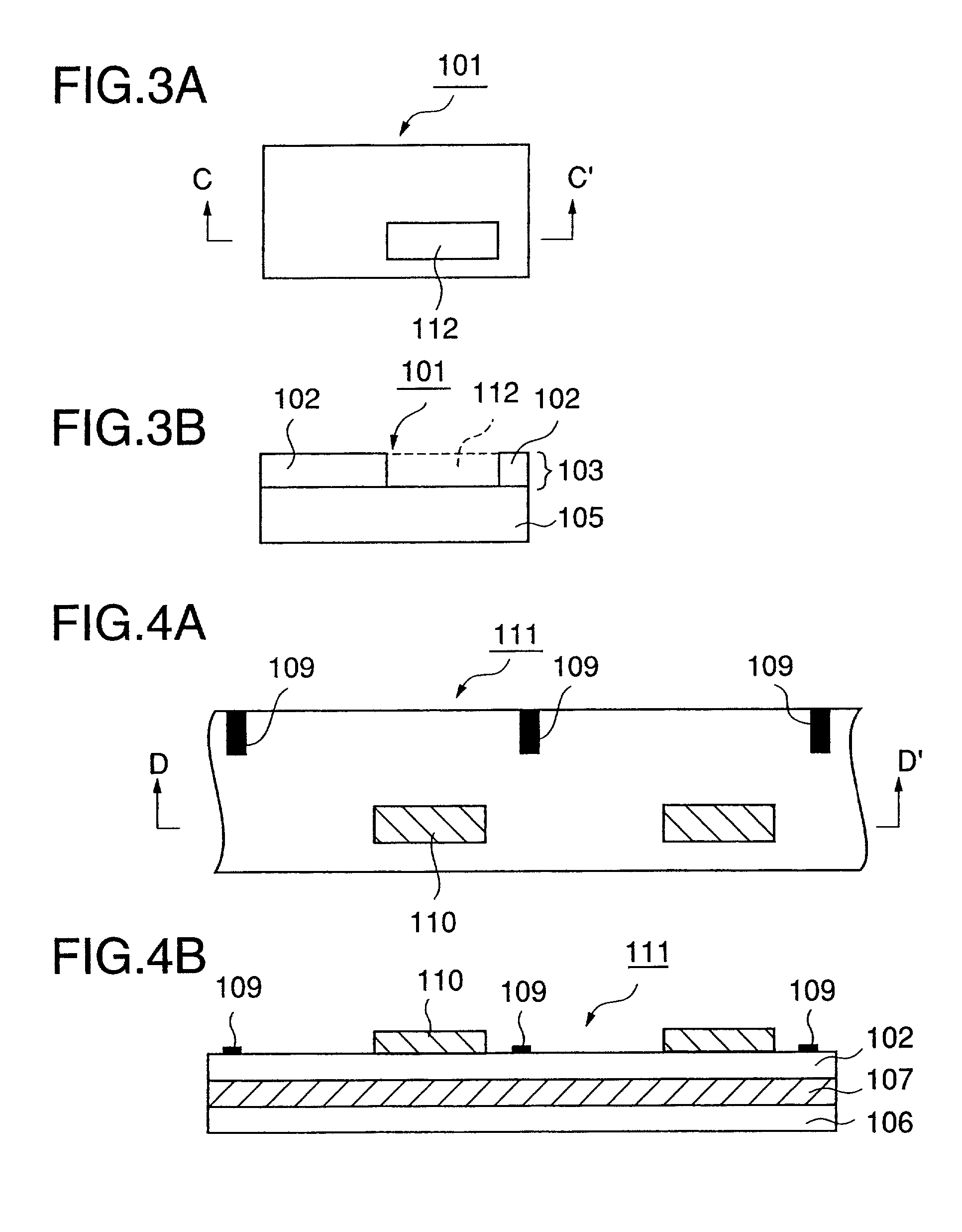
[0132]Next, the same coating liquid for a receptive layer as used in Example A1 was coated on the stripping layer, and the coating was dried to form a receptive layer in a blotted form as shown in FIGS. 3 and 4 at a coverage of 2.0 g / m2 on a dry basis.

[0133]Next, a masking layer ink having the following composition was gravure printed in a pattern as shown in FIGS. 3 and 4 on the receptive layer to form a masking layer at a coverage of 2.0 g / m2 on a dry basis.

[0134]

(Masking layer ink)Acrylic resin50 partsPolyethylene wax50 partsMethyl ethyl ketone25 partsToluene25 parts

[0135]Further, the same detection mark ink as used in Example A1 was gravure printed in a pattern as sh...

example a3

[0136]The same substrate film as used in Example A1 was provided. The same detection mark ink as used in Example A1 was gravure printed in a pattern as shown in FIGS. 5 and 6 on the surface of the substrate film to form a detection mark at a coverage of 1.5 g / m2 on a dry basis. Further, the same coating liquid for a stripping layer as used in Example A1 was coated, and the coating was dried to form a stripping layer having a given pattern, as shown in FIGS. 5 and 6, at a coverage of 2.0 g / m2 on a dry basis on the whole area (on the detection mark) of the substrate film while partially ensuring a portion not provided with the stripping layer.

[0137]The same coating liquid for a receptive layer as used in Example A1 was then coated and superimposed on the stripping layer in the same pattern as in the stripping layer, as shown in FIGS. 5 and 6, and the coating was dried to form a receptive layer at a coverage of 2.0 g / m2 on a dry basis. Thus, an intermediate transfer recording medium of...


PUM

PropertyMeasurementUnit
thicknessaaaaaaaaaa
distanceaaaaaaaaaa
thermal transferaaaaaaaaaa

Abstract

There is provided a print which has been produced by providing an intermediate transfer recording medium comprising a substrate film and a transfer portion, comprising at least a receptive layer, provided separably on the substrate film, forming a thermal transfer image onto the transfer portion, and retransferring the transfer portion onto an object while accurately and stably forming a non-transferred portion onto a part of the object and, in addition, does not increase a production cost for providing a final print. The intermediate transfer recording medium comprises a substrate film and a transfer portion comprising at least a receptive layer, the transfer portion being provided separably on the substrate film. The print has on its at least one side a transfer portion-non-retransferred portion.

Description

BACKGROUND OF THE INVENTION[0001]1. Field of the Invention[0002]The present invention relates to an intermediate transfer recording medium comprising a substrate film and a transfer portion, which is provided separably on the substrate film and comprises at least a receptive layer, a print formed by providing the intermediate transfer recording medium, thermally transferring an image onto the transfer portion, and then retransferring the transfer portion onto an object, and a method for image formation using the intermediate transfer recording medium.[0003]2. Prior Art[0004]Thermal transfer has become extensively used as a simple printing method. The thermal transfer is a method which comprises the steps of: putting a thermal transfer sheet, comprising a colorant layer provided on one side of a substrate sheet, on top of a thermal transfer image-receiving sheet optionally provided with an image-receptive layer; and image-wise heating the backside of the thermal transfer sheet by hea...

Claims


Application Information

Patent Timeline
Patent Type & Authority Patents(United States)
IPC IPC(8): B41M5/035B41M5/30B41M5/00B41M5/025B41M5/52G06K1/12
CPCB41M5/0256G06K1/121B41M5/52B41M5/035
Inventor OSHIMA, KATSUYUKIODAMURA, KOZOIMAI, TAKAYUKI
Owner DAI NIPPON PRINTING CO LTD
Why Eureka
Try Eureka