
Scintillating nanocomposites

a nano-composite and nano-composite technology, applied in the direction of instruments, nuclear engineering, conversion screens, etc., can solve the problems of deterioration of the transparency of the scintillator nano-composite, deformation of the final product, etc., and achieve the effect of high quality, less complicated, and high-quality scintillator materials

Active Publication Date: 2021-03-23
KONINKLJIJKE PHILIPS NV
View PDF14 Cites 0 Cited by
  • Summary
  • Abstract
  • Description
  • Claims
  • Application Information

AI Technical Summary

Benefits of technology

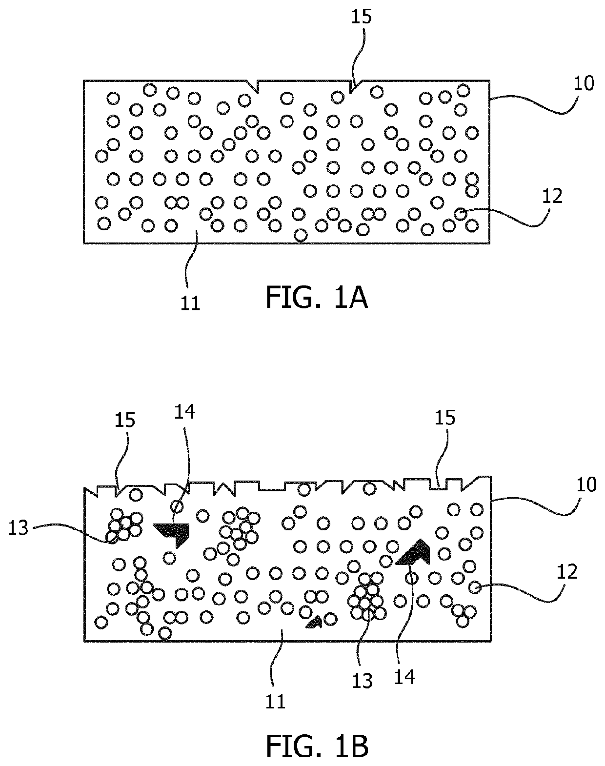
This patent describes a new method for making a high-quality transparent scintillator composite by using nanoparticle powders. The method involves using a precursor to the first matrix material as a dispersing agent, which eliminates the need to remove the dispersing medium and prevents defects in the final product. The resulting nanocomposite has improved quality and can be used in applications like radiation detectors. The method is simpler and more efficient than existing methods and produces better quality scintillators. The resulting transparent scintillator has improved quality and can be used in imaging systems.

Problems solved by technology

By using a precursor to the first matrix material as a dispersing agent, it does not have to be removed, obviating a process step that is energy consuming and, even more importantly, causes defects in the final product that deteriorates transparency of the scintillator nanocomposite.

Method used


Image

  • Scintillating nanocomposites
  • Scintillating nanocomposites
  • Scintillating nanocomposites

Examples


example 1

Polyurethane Filled with Y3Al5O12:1% Ce Nanoparticles (˜20 Vol. %)

[0040]11.498 g of Aluminium isopropoxide, 11.336 g of Yttrium acetate hydrate and 0.111 g of Cerium acetate hydrate were blended together with mixture of solvents: 1,4-butanediol and diethylene glycol in mass ratio 9:1. The colloidal solution was stirred on a hot plate for 3 hours with mild heating of 50 degrees Celsius. After the mixture was homogenized, it was poured into a high pressure autoclave vessel. Air present in the autoclave was flushed away with Argon before the mixture was heated to 225 degrees Celsius for 60 hours with a heating rate 1.5 degrees Celsius / min. At the end of process the mixture was cooled down to obtain a translucent yellowish suspension.

[0041]Next, 9 g of the obtained dehydrated suspension was rapidly mixed with 16 g of dehydrated 1,6-diisocyanatohexane and 1 drop of dibutyltin dilaurate. The viscous material was poured out into Teflon mold and kept in an oven at 60 degrees Celsius for 8 h...

example 2

Polyurethane Gel (PU Gel) Filled with Lu2Gd1Al5O12:1% Ce Nanoparticles (˜35 Vol. %)

[0046]6.008 g of Aluminium isopropoxide, 7.529 g of Lutetium acetate hydrate, 3.350 g of Gadolinium acetate hydrate and 0.104 g of Cerium acetate hydrate were blended together with mixture of solvents: 1,4-butanediol and diethylene glycol in mass ratio 9:1. The colloidal solution was stirred on a hot plate for 3 hours with mild heating of 50° C. After the mixture was homogenized, it was poured into a high pressure autoclave vessel. Air present in autoclave was flushed away with Argon. The mixture was heated to 225 degrees Celsius for 60 hours with a heating rate 1.5 degrees Celsius / min. At the end of process the mixture was cooled down and translucent yellowish suspension was obtained.

[0047]5 g of the obtained dehydrated suspension was rapidly mixed with 6.5 g of mixture of Polymeric MDI (a mixture of oligomeric polyisocyanates) and an MDI isomer (isocyanates (1-isocyanato-4-[(4 isocyanatophenyl)methy...


PUM

PropertyMeasurementUnit
diameteraaaaaaaaaa
diameteraaaaaaaaaa
pressureaaaaaaaaaa

Abstract

An improved scintillator nanocomposite comprising nanoparticles with scintillating properties and a diameter between 10 and 50 nanometer and a first matrix material comprises is obtained by introducing the nanoparticles into a dispersing medium to form a stable suspension. The dispersing medium is a precursor to the first matrix material, which is cured to form the first matrix material.

Description

CROSS REFERENCE TO RELATED APPLICATIONS[0001]This application is the U.S. National Phase application under 35 U.S.C. § 371 of International Application No. PCT / EP2016 / 076763, filed Nov. 7, 2016, published as WO 2017 / 084898 on May 26, 2017, which claims the benefit of European Patent Application Number 15195392.4 filed Nov. 19, 2015. These applications are hereby incorporated by reference herein.FIELD OF THE INVENTION[0002]The present invention generally relates to a method for producing a scintillator nanocomposite, a scintillator nanocomposite, a product comprising a scintillator nanocomposite, a method to produce a transparent scintillator, a transparent scintillator, a radiation detector and an imaging system.BACKGROUND OF THE INVENTION[0003]Radiation detection materials, such as phosphors, are used in many applications, e.g. as scintillator materials in security or medical scanners, such as x-ray, CT, PET or SPECT scanners. These materials are usually used in single crystal form...

Claims


Application Information

Patent Timeline
Patent Type & Authority Patents(United States)
IPC IPC(8): G01T1/203G21K4/00C09K11/77G01T1/16C09K11/02B82Y15/00B82Y20/00B82Y40/00
CPCG01T1/2033C09K11/02C09K11/025C09K11/7721C09K11/7774G01T1/1606G01T1/203G21K4/00B82Y15/00B82Y20/00B82Y40/00
Inventor WIATROWSKA, ANETAWIECZOREK, HERFRIED KARLRONDA, CORNELIS REINDERKEUR, WILHELMUS CORNELISNACHMAN, MALGORZATA
Owner KONINKLJIJKE PHILIPS NV
Learn More