Supercharge Your Innovation With Domain-Expert AI Agents!

Optical sensing circuit with voltage to current converter for pointing device

a technology of optical sensing circuit and voltage converter, which is applied in the direction of pulse generator, pulse technique, instruments, etc., can solve the problems of increasing the cost of the pointing device itself, the inability to identify the rotational direction of the rotary slit xslt, etc., and achieves the effect of lowering the voltage and lowering the voltag

Inactive Publication Date: 2006-01-10
KK TOSHIBA
View PDF6 Cites 7 Cited by
  • Summary
  • Abstract
  • Description
  • Claims
  • Application Information

AI Technical Summary

Benefits of technology

[0024]a voltage to current conversion circuit to be connected between a output terminal of a light detector, which terminal output a voltage in accordance with the amount of detected light from a light source, and a second power supply terminal, configured to lower the voltage at the output terminal at by increasing a value of current flowing from the output terminal to the second power supply terminal as the voltage at the output terminal is lowered, and
[0034]a first voltage to current conversion circuit configured to lower the voltage at the first output terminal by increasing a value of current flowing from the first output terminal as the voltage at the first output terminal is lowered;
[0035]a second voltage to current conversion circuit configured to lower the voltage at the second output terminal by increasing a value of current flowing from the second output terminal as the voltage at the second output terminal is lowered;

Problems solved by technology

However, the following problems have been inherent in such a conventional optical sensing circuit.
Also in such a case, it is impossible to identify the rotational direction of the rotary slit XSLT.
If measures taken to counter such a phenomenon depend on mechanical structures or arrangements of the LED, the rotary slit and the phototransistors, the cost of the pointing device itself may be increased.

Method used


Image

  • Optical sensing circuit with voltage to current converter for pointing device
  • Optical sensing circuit with voltage to current converter for pointing device
  • Optical sensing circuit with voltage to current converter for pointing device

Examples


first embodiment

(1) First Embodiment

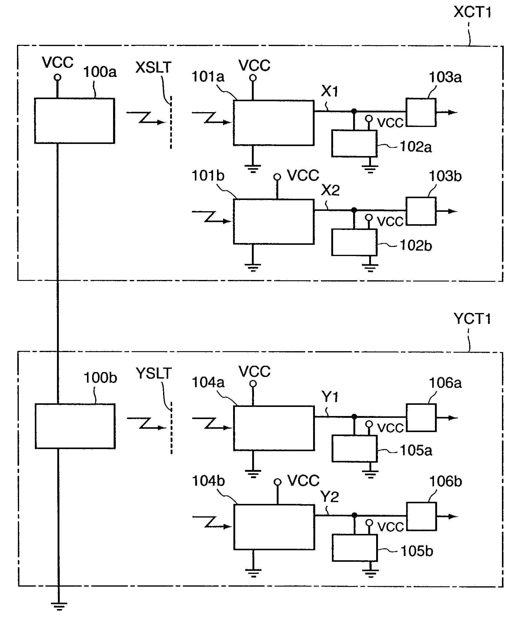
[0063]FIG. 4 shows a constitution of an optical sensing circuit according to a first embodiment of the present invention. This circuit comprises a circuit XCT1 for detecting a moving amount in the X direction of a pointing device and its direction, and a circuit YCT1 for detecting a moving amount in the Y direction and its direction. The circuit XCT1 has an X light emitting portion 100a, X photodetectors 101a, 101b, variable current sources 102a, 102b, and comparators 103a, 103b. The circuit YCT1 has a Y light emitting portion 100b, Y photodetectors 104a, 104b, variable current sources 105a, 105b, and comparators 106a, 106b.

[0064]The X light emitting portion 100a and the Y light emitting portion 100b are connected in series between a power supply voltage VCC terminal and a ground voltage VSS terminal to emit light.

[0065]In the circuit XCT1, the light emitted from the X light emitting portion 100a is received by the X photodetectors 101a and 101b through a rotary...

second embodiment

(2) Second Embodiment

[0072]A second embodiment of the present invention corresponds to the first embodiment but realized by a more specific circuit.

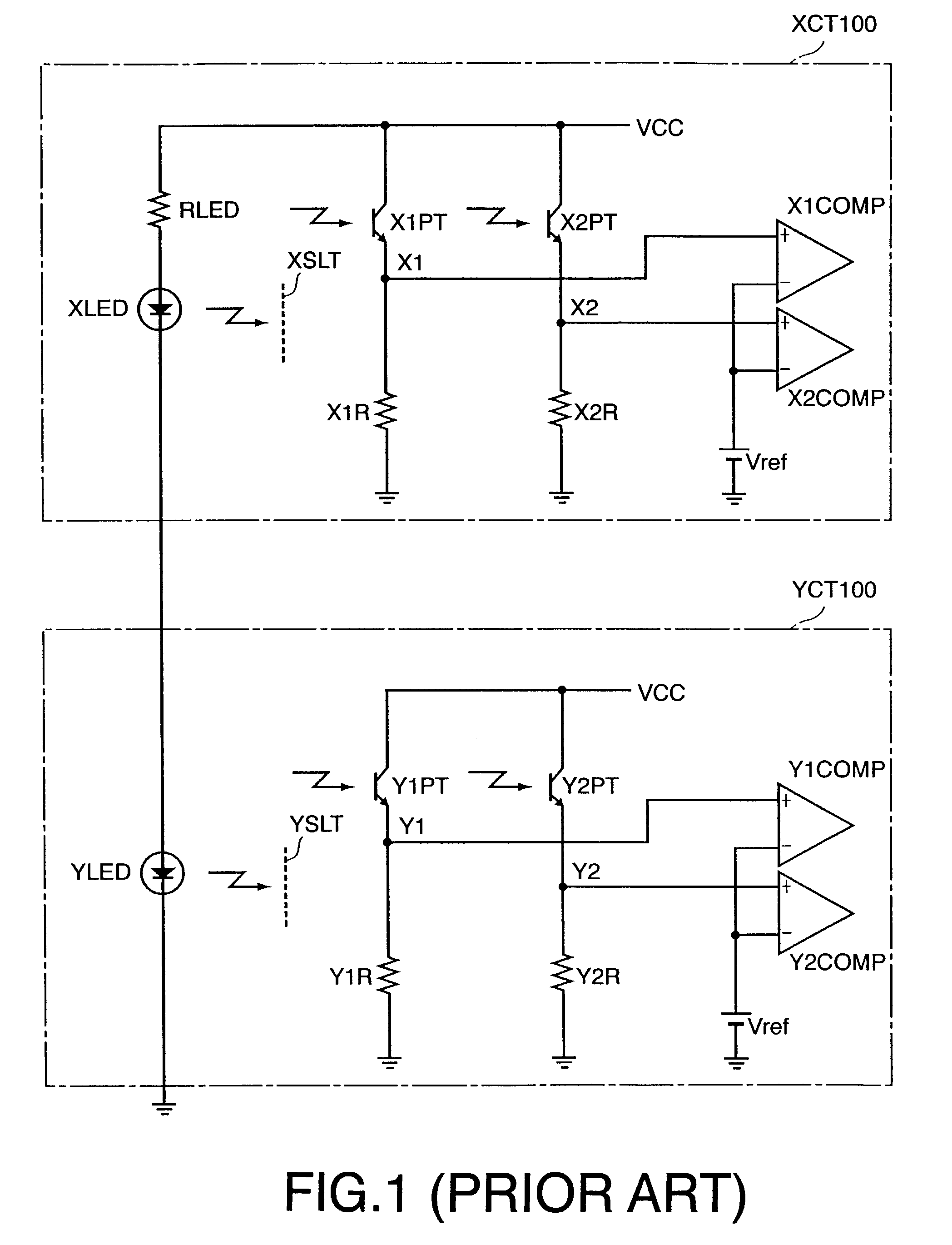
[0073]FIG. 6 shows a constitution of an optical sensing circuit of the second embodiment. Correspondence to the first embodiment is as follows. That is, the circuit XCT1 for detecting the X-direction movement corresponds to a circuit XCT2, the rotary slit XSLT to a rotary slit XSLT, the X light emitting portion 100a to an LED XLED, the X photodetector 101a to a phototransistor X1PT and a resistor X1R, the X photodetector 101b to a phototransistor X2PT and a resistor X2R, the comparator 103a to a comparator X1COMP, the comparator 103b to a comparator X2COMP, the variable current source 102a to a voltage detection circuit VDC1 and a voltage to current conversion circuit V / C·CONV1, the variable current source 102b to a voltage detection circuit VDC2 and a voltage to current conversion circuit V / C·CONV2.

[0074]Additionally, the circuit YCT1 f...

third embodiment

(3) Third Embodiment

[0098]In the aforementioned second embodiment, as shown in FIG. 7, the gate of the P channel MOS transistor M1 is grounded, and transistor M1 is always maintained ON. On the other hand, according to the third embodiment, as shown in FIG. 11, a control signal CTL is input to a gate of a transistor M1. This control signal CTL is applied by, for example, a central processing unit of a not-shown computer. For example, a control signal which becomes a low level when a pointing device is in an operating state and a high level when it is in a suspended state is input to the gate of the transistor M1, and accordingly the transistor M1 is turned OFF in the suspended state. Thus, the entire circuit is not operated, and wasteful current consumption can be prevented. Since the low-level control signal CTL is applied to turn ON the transistor M1 when the pointing device is in the operating state, an operation is similar to that of the second embodiment.


PUM


Abstract

An optical sensing circuit is provided with a light detector, a voltage to current conversion circuit connected to the light detector, and a comparator. The voltage to current conversion circuit includes an electric resistor and a current mirror circuit connected in parallel to the resistor. The voltage to current conversion circuit increases an electric current flowing through the circuit as a voltage of the output of the light detector decreases. The comparator compares the voltage of the output of the light detector with a reference voltage.

Description

CROSS-REFERENCE TO RELATED APPLICATIONS[0001]This application is based upon and claims the benefit of priority from prior Japanese Patent Application No. P2002-051979, filed on Feb. 27, 2002; the entire contents of which are incorporated herein by reference.FIELD OF THE INVENTION[0002]The present invention relates to an optical sensing circuit, and more particularly, to a circuit suitable for producing a signal used for detecting a moving amount and a moving direction in a pointing device referred to as a so-called mouse in a computer.BACKGROUND OF THE INVENTION[0003]FIG. 1 shows a constitution of a conventional optical sensing circuit used for a pointing device. A circuit XCT 100 is provided for producing an X signal indicating a moving amount in an X direction and a moving direction, and a circuit YCT 100 is provided for producing a Y signal indicating a moving amount in a Y direction and a moving direction.[0004]Between a power supply voltage VCC terminal and a ground voltage VSS...

Claims


Application Information

Patent Timeline
IPC IPC(8): H01J40/14G01B11/00G01J1/42G01J1/44G06F3/038G06F3/042H01L31/12
CPCG06F3/0312
Inventor BAN, TAKAYUKIHASHIMOTO, MASARU
Owner KK TOSHIBA
Features
  • R&D
  • Intellectual Property
  • Life Sciences
  • Materials
  • Tech Scout
  • Unparalleled Data Quality
  • Higher Quality Content
  • 60% Fewer Hallucinations
Learn More