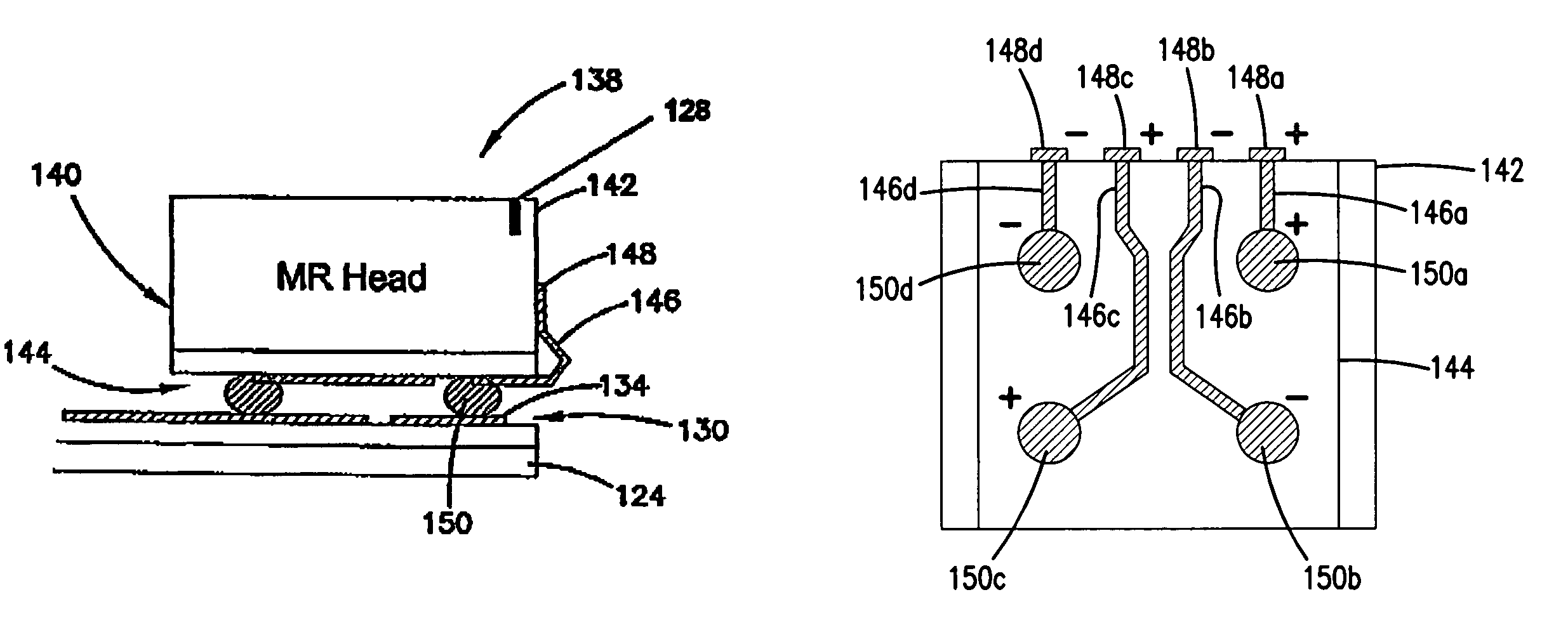
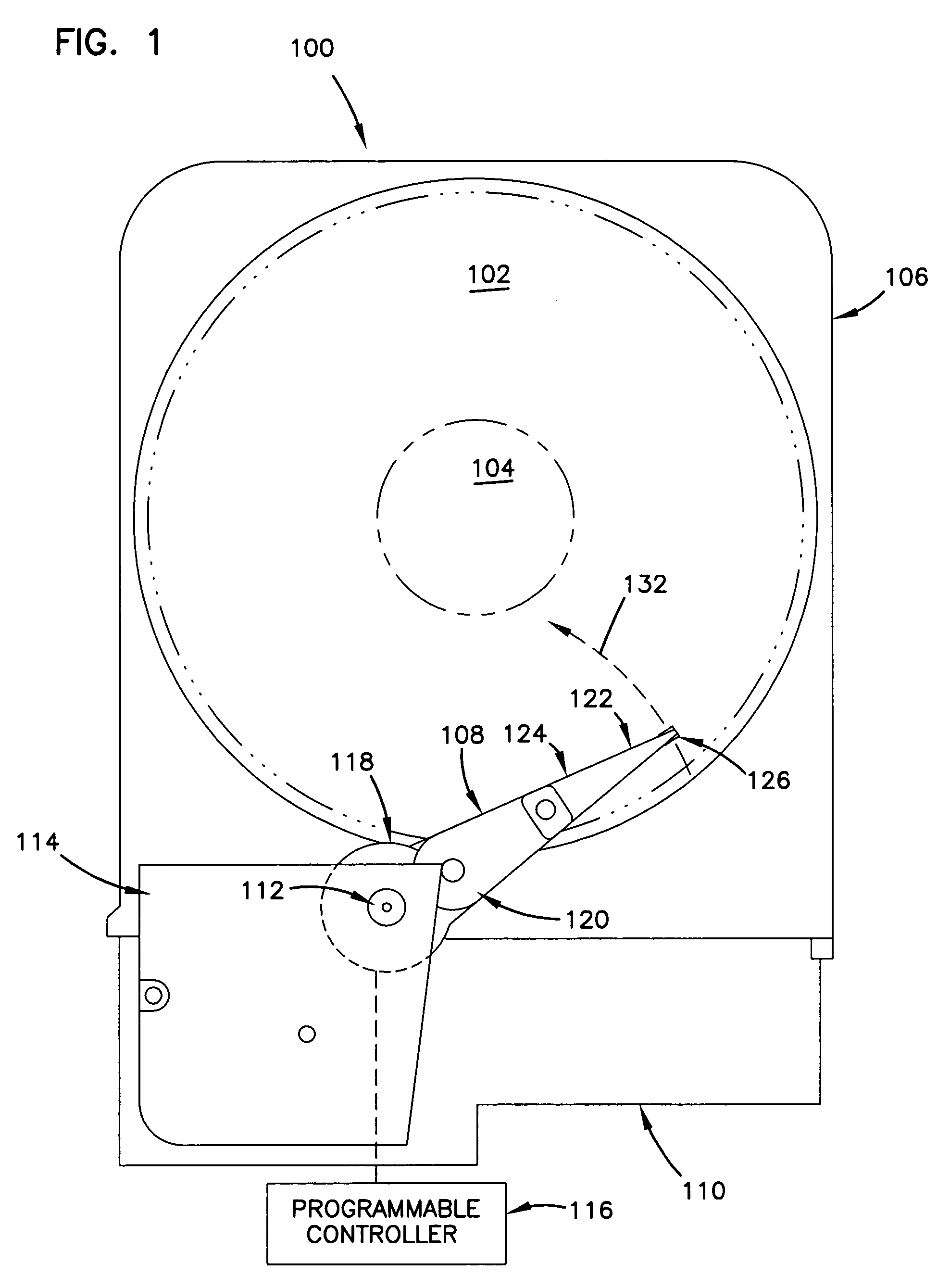
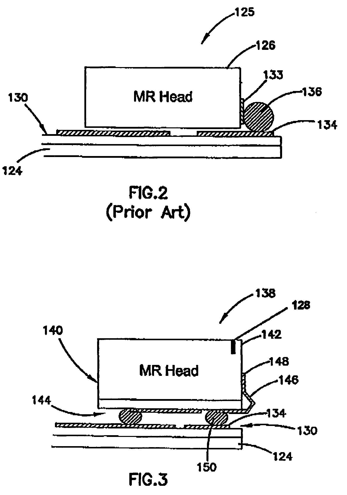
Head gimbal assembly with flex circuit arrangement between slider and head interconnect assembly
- Summary
- Abstract
- Description
- Claims
- Application Information
AI Technical Summary
Benefits of technology
Problems solved by technology
Method used
Image
Examples
second embodiment
[0051]FIG. 7 illustrates an alternative, second embodiment of a bonding assembly 152 having a slider scale package 154 of a slider / MR head 156 and a flex circuit 158 for electrically connecting the slider / MR head 156 to the head interconnect circuit 130 on the suspension 124.
[0052]In FIG. 7, the flex circuit 158 includes a conductive material 160, preferably copper. One end of the conductive material 148 is bent upwardly and electrically connected and bonded to a bond pad 162 of the slider / MR head 142. The bond pad 162 is disposed at the back of the slider / MR head 156, as opposed to at the front end of the slider / MR head 142 as shown in FIG. 3. Similarly, the bonding can be done by a variety of ways, such as solder, conductive adhesive, etc. The flex circuit 158 also includes an interconnect pad 164 disposed at the other end of the conductive material 160. As shown, the interconnect pad 164 is positioned at the back of the slider / MR head 156 and is electrically bonded to the conduct...
third embodiment
[0055]FIG. 10 illustrates an alternative, third embodiment of a bonding assembly 166 having a slider scale package 168 of a slider / MR head 170 and a flex circuit 172 for electrically connecting the slider / MR head 170 to the head interconnect circuit 130 on the suspension 124.
[0056]In FIG. 10, the flex circuit 172 includes a conductive material 174, preferably copper. One end of the conductive material 174 is electrically connected and bonded to a bond pad 176 of the slider / MR head 170 via a bonding ball 178. The bond pad 176 is disposed at the back of the slider / MR head 170. Similarly, the bonding can be done by a variety of ways, such as solder, conductive adhesive, etc. The flex circuit 172 also includes an interconnect pad 180 disposed at the other end of the conductive material 174. As shown, the interconnect pad 180 is positioned at the back of the slider / MR head 170 and is electrically bonded to the conductive material 134 of the head interconnect circuit 130. Similarly, the b...
fourth embodiment
[0057]FIG. 11 illustrates an alternative, fourth embodiment of a bonding assembly 182 having a slider scale package 184 of a slider / MR head 186 and a flex circuit 188 for electrically connecting the slider / MR head 186 to the head interconnect circuit 130 on the suspension 124.
[0058]In FIG. 11, the flex circuit 188 includes a conductive material 190, preferably copper. One end of the conductive material 190 is electrically connected and bonded to a bond pad 192 of the slider / MR head 186 via a bonding ball 194. The bond pad 192 is disposed at the front end of the slider / MR head 186, as opposed to at the back end of the slider / MR head 186. Similarly, the bonding can be done by a variety of ways, such as solder, conductive adhesive, etc. The flex circuit 188 also includes an interconnect pad 196 disposed at the other end of the conductive material 190. As shown, the interconnect pad 196 is positioned at the back of the slider / MR head 186 and is electrically bonded to the conductive mate...
PUM
 Abstract
Description
Claims
Application Information
 - R&D
- Intellectual Property
- Life Sciences
- Materials
- Tech Scout
- Unparalleled Data Quality
- Higher Quality Content
- 60% Fewer Hallucinations
Browse by: Latest US Patents, China's latest patents, Technical Efficacy Thesaurus, Application Domain, Technology Topic, Popular Technical Reports.
© 2025 PatSnap. All rights reserved.Legal|Privacy policy|Modern Slavery Act Transparency Statement|Sitemap|About US| Contact US: help@patsnap.com


