
Integrated circuit selective power down protocol based on acknowledgement

a technology of acknowledgement and integrated circuits, applied in the field of integrated circuits, can solve the problems of presenting cost, duration, weight and dimension, and most socs cannot be controlled in such a manner, and achieve the effect of accurate control of shutdown

Inactive Publication Date: 2006-01-10
ERIDANUS TECH
View PDF12 Cites 40 Cited by
  • Summary
  • Abstract
  • Description
  • Claims
  • Application Information

AI Technical Summary

Benefits of technology

"The invention is about controlling the shutdown of different types of circuits in a single system to preserve their necessary function. This is achieved by switching off the system clock for portions of the circuit blocks that are temporarily unnecessary. A power control manager determines which circuit blocks should receive a shutdown signal and which ones should continue operating based on their local clock signals. The circuit blocks provide an acknowledgement signal to the power control manager when they are ready to restart. The technical effect of this invention is to improve the efficiency and reliability of a system-on-chip by selectively powering down unnecessary circuits while still ensuring their necessary function."

Problems solved by technology

Such applications generally require a battery or some sort of power supply, which typically presents cost, duration, weight and dimension issues.
Although the idea of separating the system clock from the various IP blocks is compelling, most SOCs cannot be controlled in such a manner.
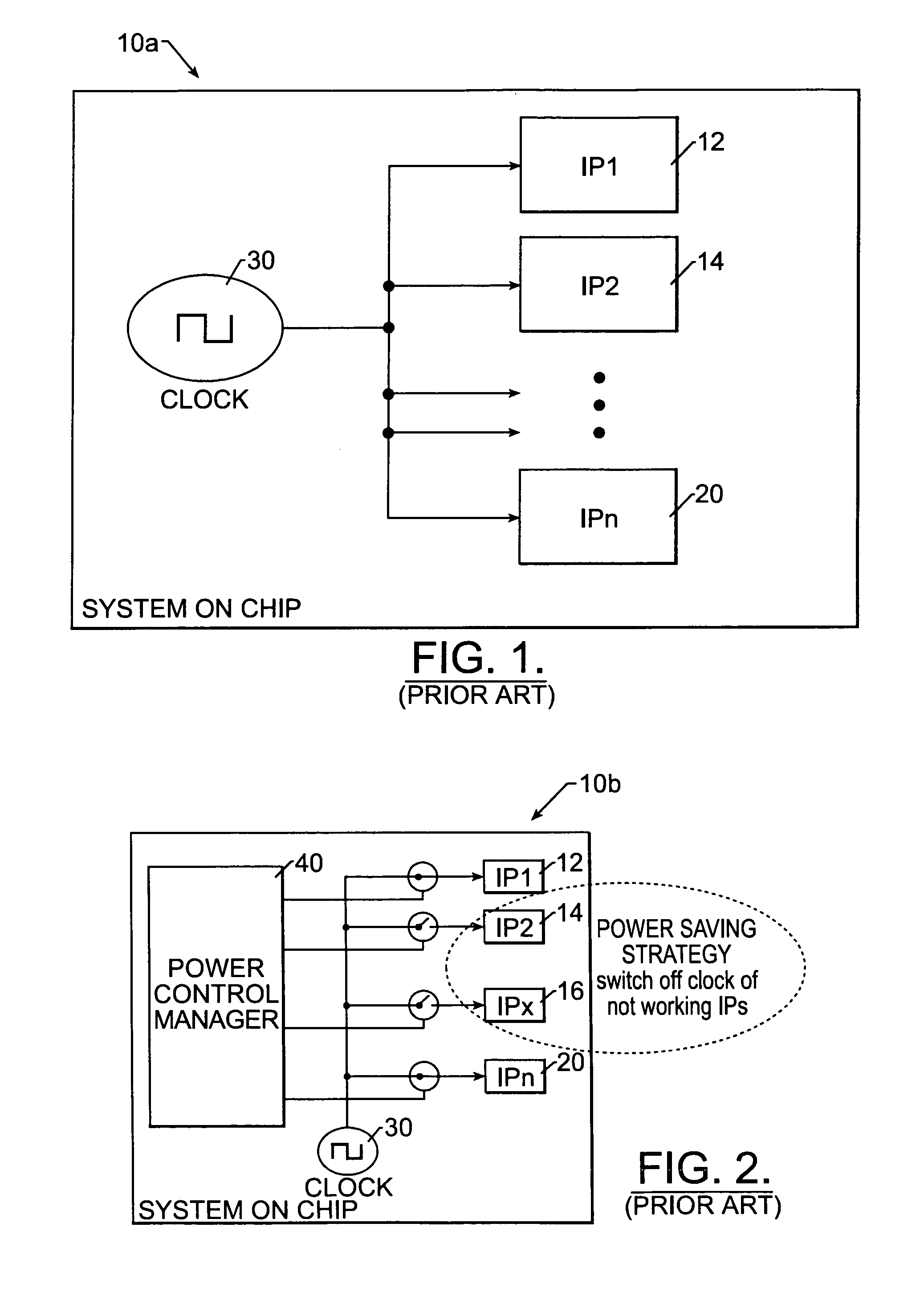
The implementation of such a system as shown in FIG. 2 causes problems.
It can therefore be difficult to establish an exact time when it is possible to switch off the clock to an IP block without causing errors.
In some cases, if the clock to the IP block is stopped abruptly, there is a risk of preventing a critical operation of the block from being carried out.
Additionally, removing a system clock from a counter or a timing signal generator could be fatal to that particular IP block.
Separating the system clock 30 from the IP block 18 could seriously degrade such accuracy.

Method used


Image

  • Integrated circuit selective power down protocol based on acknowledgement
  • Integrated circuit selective power down protocol based on acknowledgement
  • Integrated circuit selective power down protocol based on acknowledgement

Examples


Embodiment Construction

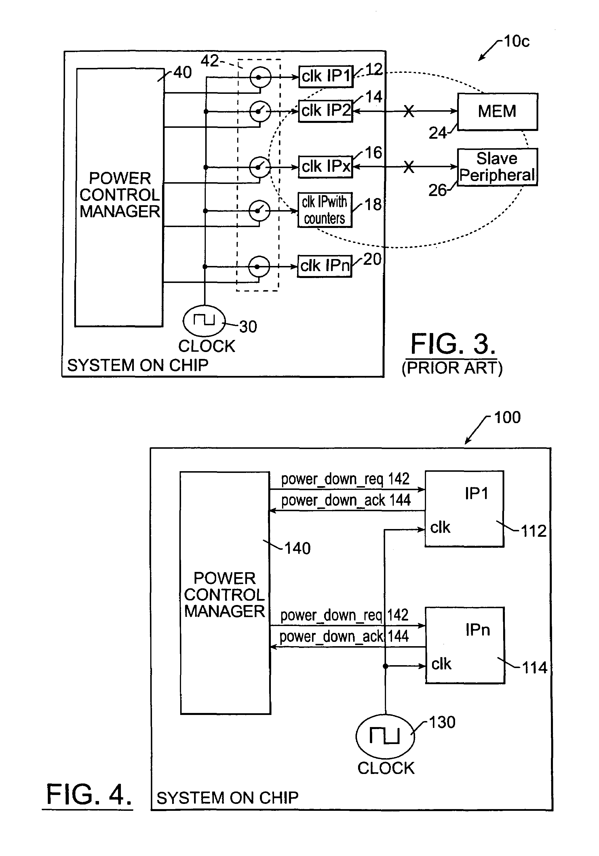
[0027]FIG. 4 illustrates interconnections that can be used to implement the protocol according to the invention. An SOC 100 includes a system clock 130, a power control manager 140, and two IP blocks 112 and 114. The system clock 130 is provided to each of the IP blocks 112, 114. Additionally, two signal lines couple each IP block 112, 114 to the power control manager 140. The first of these is a power down request line 142, and the second is a power down acknowledgment line 144. Each IP block 112, 114 has its own set of request and acknowledgment lines 142, 144 coupled to the power control manager 140. Of course any number of IP blocks 112, 114, etc. could be included in the SOC 100, with only the addition of the required number of request and acknowledgment lines 142, 144 and the proper connections to the system clock 130 being necessary.

[0028]In operation, each IP block 112, 114 receives a “power down request” signal on the power down request line 142. A signal of either a 0 or a...


PUM


Abstract

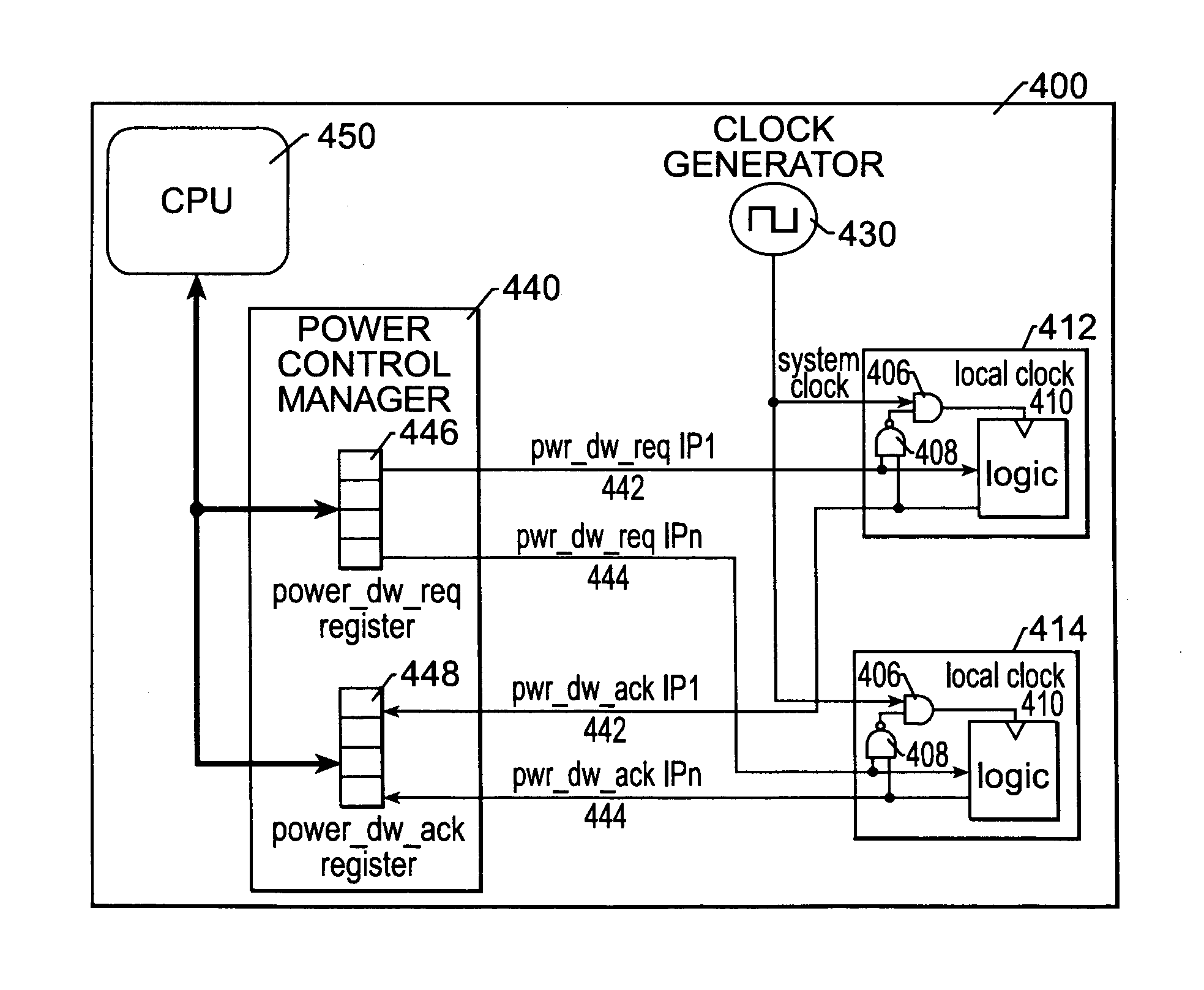
A system-on-chip (SOC) includes a power down circuit. Within the SOC are several circuit blocks, each of them operating responsive to a local clock signal. A system clock is coupled to the circuit blocks for providing a system clock signal that functions as the local clock signal for selected circuit blocks. A power control manager provides a signal that at least partially determines whether the system clock will act as the local clock for some of the circuit blocks. Within the circuit blocks is a shutdown circuit that selectively prevents the system clock signal from functioning as the local clock signal in those circuit blocks that receive the shutdown signal, but the shutdown circuit only operates after both the signal to shutdown is received from the power control manager and after the circuit block has, in fact, shutdown.

Description

FIELD OF THE INVENTION[0001]The present invention is directed to integrated circuits, and more particularly, to a power down circuit for reducing power consumption in a system-on-chip (SOC) comprising a plurality of circuit blocks by switching off the system clock to selected circuit blocks that are temporarily unnecessary.BACKGROUND OF THE INVENTION[0002]Current trends in integrated circuit designs call for creating an entire manufactured circuit system on a single chip. Such a system is termed system-on-chip or SOC. This differs from simple circuit integration in that many different types of circuits can be included on a single chip. For example, an SOC could include a computer processor, various signal processors, a large amount of memory, various clocks, power down circuits, and necessary system controllers all integrated on a single piece of silicon or integrated into a single package. This level of integration was not previously possible with prior integration techniques, and ...

Claims


Application Information

Patent Timeline
Patent Type & Authority Patents(United States)
IPC IPC(8): G06F1/04G06F1/32
CPCG06F1/3203G06F1/3287G06F1/3243Y02B60/1282Y02B60/32Y02B60/1239Y02D10/00Y02D30/50
Inventor ALIA, MICHELECARRANO, MICHELEPISTRITTO, CARMELO
Owner ERIDANUS TECH
Learn More