
Extendable joined wing system for a fluid-born body

a fluid-born body and joined wing technology, which is applied in the field of expanding joined wing systems for fluid-born bodies, can solve the problems of difficult design of deployable wings that offer high efficiency, large external packaging volume needed for housing the mechanism, and complex diamond back mechanisms. , to achieve the effect of increasing aerodynamic efficiency, reducing the size of the wing, and increasing the wing length

Inactive Publication Date: 2006-01-17
KAZAK COMPOSITES
View PDF10 Cites 23 Cited by
  • Summary
  • Abstract
  • Description
  • Claims
  • Application Information

AI Technical Summary

Benefits of technology

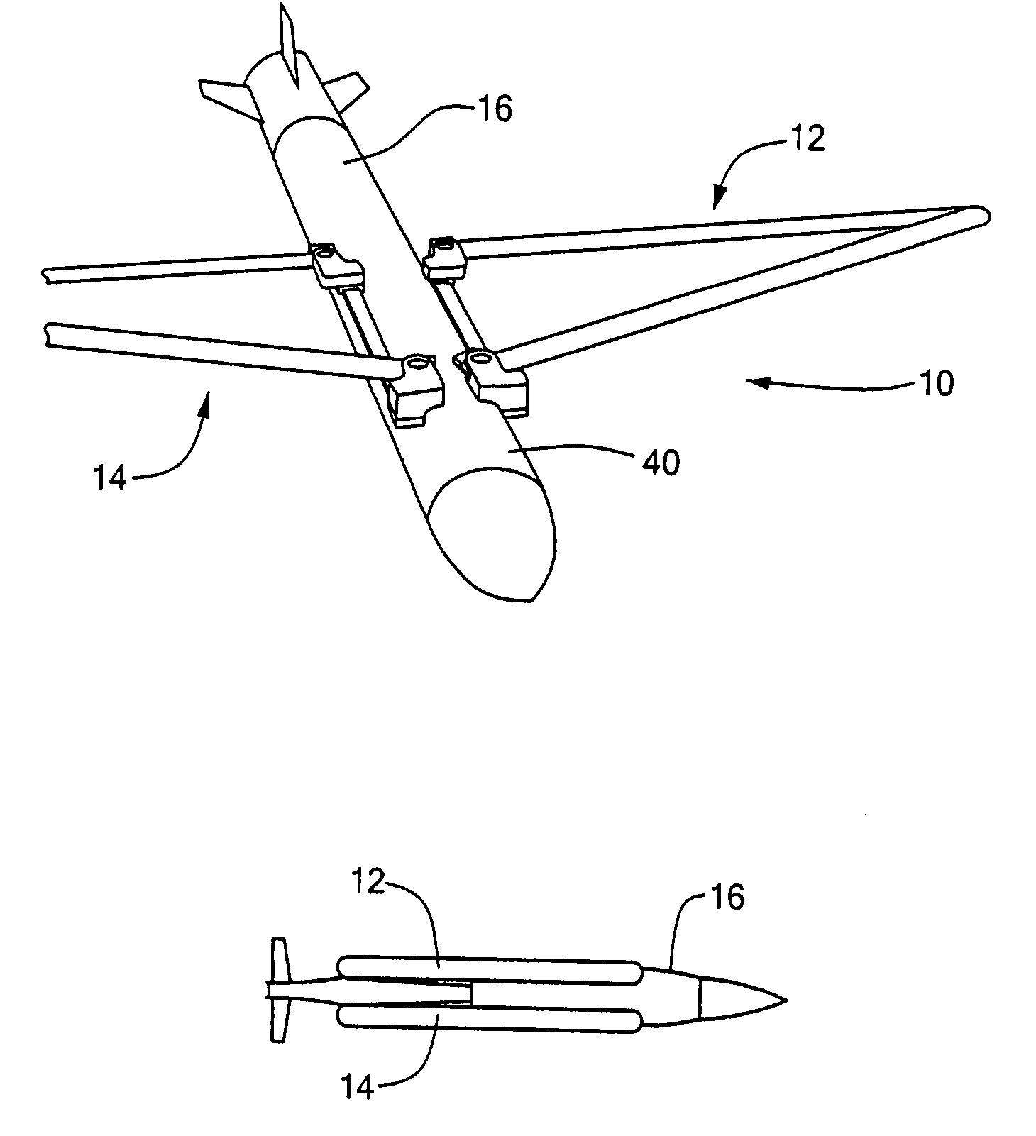
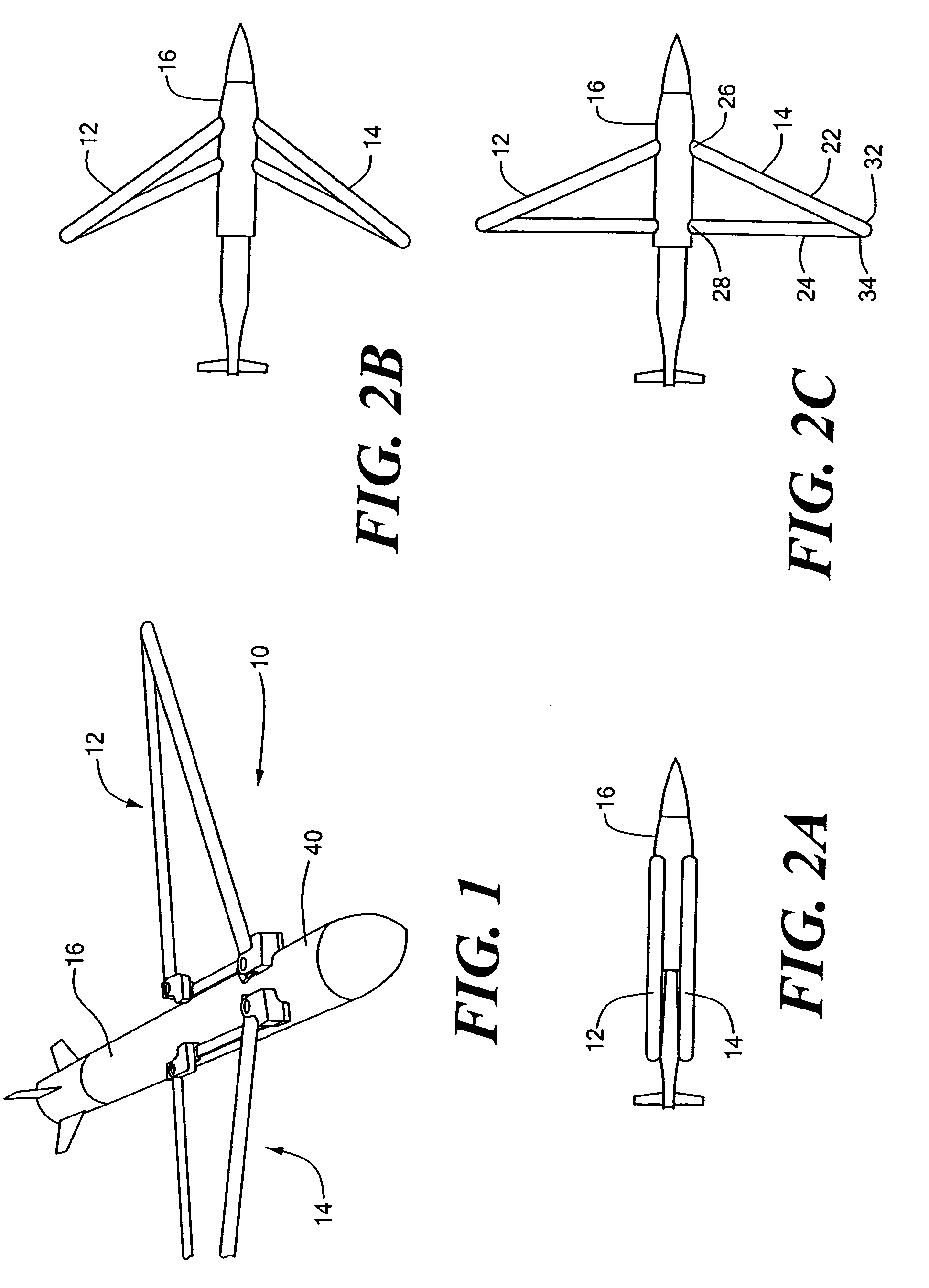
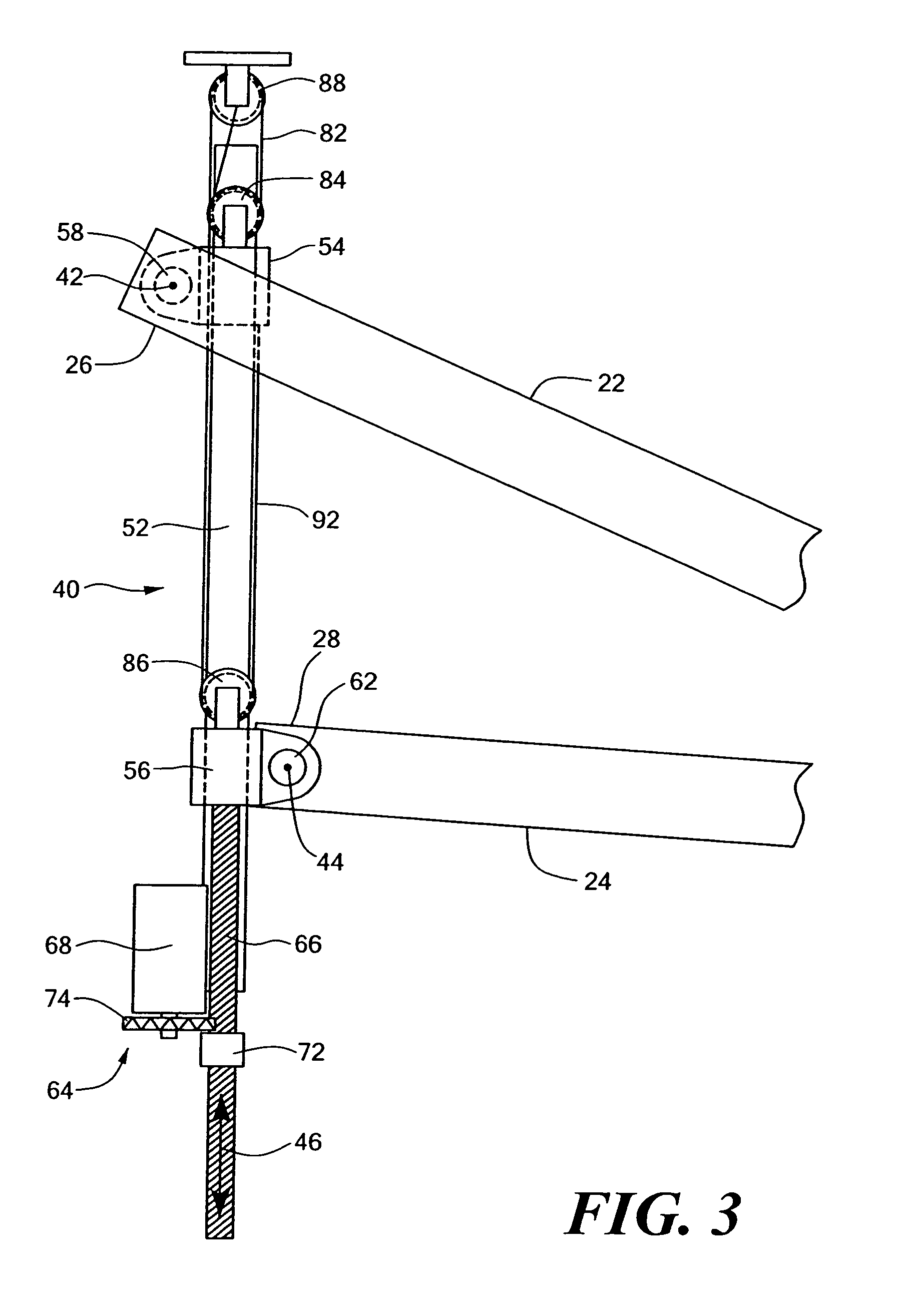
[0007]The present invention relates to an extendable joined wing system for a fluid-born body. The system has two pairs of joined wings, each pair having a forward wing and an aft wing pivotably coupled together at a point located outwardly from their roots. To extend the joined wings from a stowed position to a deployed position, a linkage mechanism mounted on the body provides both pivoting of the wing roots about a pivot point on the body and linear translation of the wing roots and their pivot points. Linear translation of the forward wing root pivot point allows the stowed wing system to occupy additional space toward the nose of the body, thereby allowing use of wings having a longer wingspan and greater aspect ratio. This results in increased aerodynamic efficiency (greater lift / drag ratio) and greater standoff range.
[0008]The linkage mechanism can also be used to incorporate flight control, such as roll and / or pitch control, directly into the wing system, reducing or eliminating separate actuators and flight surfaces, with attendant cost and weight savings and enhanced reliability. By extending or retracting the wings partially, a desired rolling and / or pitching motion can be achieved. The left and right wing pairs can be moved symmetrically or asymmetrically, depending on the desired motion. In another embodiment, actuator elements can be incorporated on or within the wings to effect flight control by deformation of the wing structure.
[0009]The forward and aft wings can be formed of any suitable material, such as a metal or a composite material. The wings can be formed in any suitable process, such as extrusion, molding, or pultrusion. Pultrusion is a suitable manufacturing process to form composite wings of a constant cross-section at low cost, with high strength and high aspect ratio.

Problems solved by technology

However, designing a deployable wing that offers high efficiency, small packaging volume, and low cost is challenging.
There are disadvantages with the diamond back type of wing also.
The diamond back is a complex mechanism and expensive to manufacture.
The external packaging volume needed to house the mechanism is considerable.

Method used


Image

  • Extendable joined wing system for a fluid-born body
  • Extendable joined wing system for a fluid-born body
  • Extendable joined wing system for a fluid-born body

Examples


example

[0050]A comparison was made of the projected aerodynamic performance of the extendable wing of the present invention with a more conventional joined wing approach in which the forward wing root pivot point remains fixed relative to the vehicle body, such as the diamond back wing. The following L / D ratios were calculated for the wings only at sea level, Mach 0.5 conditions:

[0051]

Max availableL / D @ SL,Itemwing spanM-0.5Fixed Forward57.25″19.4WingInvention79.00″23.3Improvement+21.75″ +21%

For certain air-born bodies, typical wing drag contribution is at least half the total vehicle drag in the best glide condition. Therefore, the use of the extendable wing deployment mechanism of the present invention should result in at least a 10% improvement in vehicle L / D, and a corresponding increase in glide range.

[0052]Larger span, higher aspect ratio wings have an associated aerodynamic penalty, however. As wingspan increases, the rolling moment required to initiate a turn and to counter adverse...


PUM


Abstract

An extendable wing system for a fluid-born body has a forward wing and an aft wing pivotably coupled together at a location outward of their wing roots. A linkage mechanism mounted on the body provides both pivoting of the wing roots about a pivot point and translation of the wing roots and their pivot points to extend the joined wings from a stowed position to a deployed position. Translation of the forward wing root pivot point allows the stowed wing system to occupy additional space toward the nose of the body, thereby allowing use of wings having a longer wingspan and greater aspect ratio. The linkage mechanism can also be used to incorporate flight control, such as roll and pitch control, directly into the wing system. In another embodiment, the wings can incorporate actuator elements on or within the wings to effect flight control by deformation of the wing structure.

Description

CROSS REFERENCE TO RELATED APPLICATIONS[0001]This application claims the benefit under 35 U.S.C. § 119(e) of U.S. Provisional Application No. 60 / 422,771, filed on Oct. 31, 2002, and U.S. Provisional Application No. 60 / 425,138, filed on Nov. 8, 2002, the disclosures of which are incorporated by reference herein.STATEMENT REGARDING FEDERALLY SPONSORED RESEARCH OR DEVELOPMENT[0002]The invention was made with Government support under SBIR Grant Contract # F08630-02-C-0047. The Government has certain rights in the invention.BACKGROUND OF THE INVENTION[0003]Many types of air-born bodies, both powered and unpowered, include a glide capability to increase the body's range. This is particularly the case with munitions, such as bombs, rockets, or missiles, for which a greater standoff range is desirable. Greater standoff range enhances pilot and aircraft survivability. A longer range also provides additional opportunities for maneuvering of the air-born body during flight.[0004]Increasing the...

Claims


Application Information

Patent Timeline
IPC IPC(8): F42B10/12B63B1/30B64C3/40B64C3/56B64C39/06
CPCB64C3/40B64C39/068B64C3/56B63B1/30Y02T50/145Y02T50/10
Inventor FANUCCI, JEROME P.KING, MICHAEL J.MAASS, DAVID P.BYSTRICKY, PAVEL
Owner KAZAK COMPOSITES
Learn More