Temperature compensation for silicon MEMS resonator

a technology of silicon mems and resonators, applied in the field of microelectromechanical systems, can solve problems such as s modulus, putative mems designers face a considerable challenge, and not normally be the cas

Inactive Publication Date: 2006-01-17
ROBERT BOSCH GMBH
View PDF36 Cites 124 Cited by
  • Summary
  • Abstract
  • Description
  • Claims
  • Application Information

AI Technical Summary

Benefits of technology

[0026]However, other aspects of the present invention are readily applicable to passive approaches to frequency stabilization of a resonator over an operating temperature range. For example, one method of fabricating a micromechanical resonator according to the present invention forms a beam structure and / or related support structure(s) from a first material, and the electrode, at least in part, from a second material. Where the first and second materials are properly selected with disparate thermal expansion coefficients, the relative expansion of these components with temperature will tend to passively adjust the working gap between the beam and electrode to vary a compensating stiffness applied to the beam, such that resonator frequency remains substantially stable over a prescribed temperature range.

Problems solved by technology

However, the degree to which a beam is actually “rectangular” depends on the anisotropy of the etching method used to form it.
This, however, will not normally be the case as thermally induced changes to the Young's modulus tend to change in the mechanical stiffness of the beam.
Such attempts have, however, focused on the issue of vertical oscillation compensation and have prescribing the remedial use of gold or similar materials that are incompatible with CMOS integration.
Unfortunately, the thermal coefficient of Young's modulus for silicon is in the order of 30 ppm / K.
Given nominal requirements for temperature stabilities ranging from 0.1 to 50 ppm, and common operating temperature specifications ranging from −40 C° to +85 C°, the putative MEMS designer faces a considerable challenge in the design of a temperature stable resonator.

Method used


Image

  • Temperature compensation for silicon MEMS resonator
  • Temperature compensation for silicon MEMS resonator
  • Temperature compensation for silicon MEMS resonator

Examples


Embodiment Construction

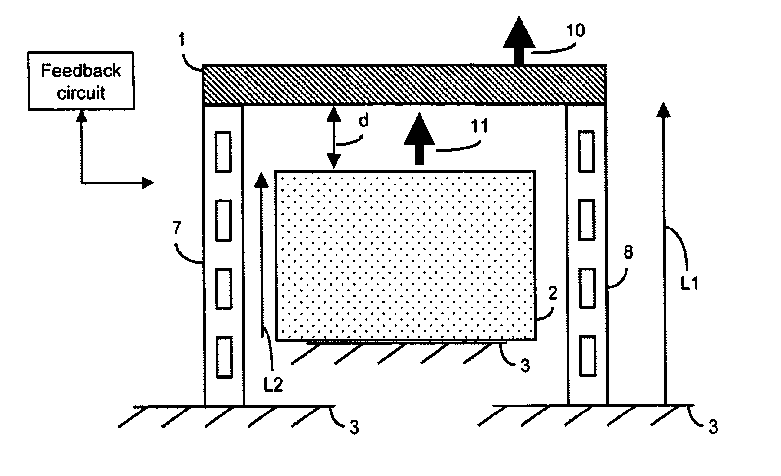
[0040]The description that follows presents several design possibilities, methods, and / or mechanical structures in surface micromachining, whereby thermally induced frequency changes in a micromechanical resonator may be remedied. According to the present invention, semiconductor compatible materials are highly preferred in the fabrication of such resonators.

[0041]Throughout the description that follows, semiconductor compatible materials are presumed in the teaching examples. This materials bias is understandable given the contemporary emphasis in CMOS integration of micromechanical structures. However, materials incompatible with such designs may also be used, albeit with fewer current design advantages. Compatible materials are not limited to silicon or silicon-based compositions, but include all materials capable of being fabricated by conventional integrated circuit techniques and / or integrated upon a semiconductor substrate. As presently preferred, resonators according to the ...


PUM

PropertyMeasurementUnit
frequencyaaaaaaaaaa
resonance frequencyaaaaaaaaaa
operating frequencyaaaaaaaaaa

Abstract

Thermally induced frequency variations in a micromechanical resonator are actively or passively mitigated by application of a compensating stiffness, or a compressive / tensile strain. Various composition materials may be selected according to their thermal expansion coefficient and used to form resonator components on a substrate. When exposed to temperature variations, the relative expansion of these composition materials creates a compensating stiffness, or a compressive / tensile strain.

Description

BACKGROUND[0001]The present invention relates generally to microelectromechanical systems (MEMS). MEMS are devices formed from miniaturized components operatively arranged on a substrate. These components are constructed through the use of lithographic and other micro-fabrication technologies to yield, for example, sensors and actuators.[0002]Many common micromechanical structures are based on the reaction (e.g., oscillation, deflection or torsion) of a beam structure to an applied force. Such beam structures usually have, or are modeled to have, a rectangular cross section. However, the degree to which a beam is actually “rectangular” depends on the anisotropy of the etching method used to form it. Beams are used in the suspension of rigid plates, as lateral oscillators, or as cantilever devices. They are a natural choice for bearing-less motion detectors. Of particular note, MEMS increasingly use beams within resonator structures as part of clock and signal filtering circuits.[000...

Claims


Application Information

Patent Timeline
Patent Type & Authority Patents(United States)
IPC IPC(8): H03H9/00H01P7/10H03HH03H9/02H03H9/24H03H9/50H03H9/54
CPCB81B3/0072H03H9/02259H03H9/02338H03H9/02448H03H9/2457H03H9/2463H03H9/02417B81B2201/0271B81B2203/0118H03H2009/02511H03H2009/02496H01P7/10H03H9/00H03H9/54
Inventor LUTZ, MARKUSPARTRIDGE, AARON
Owner ROBERT BOSCH GMBH
Why Eureka
Try Eureka