Effectively balanced dipole microstrip antenna

a dipole antenna and microstrip technology, applied in the structure the antenna feed intermediate, the resonance antenna, etc., can solve the problems of reducing the efficiency of the radiating elemen

Inactive Publication Date: 2006-01-17
DRNC HLDG INC
View PDF6 Cites 149 Cited by
  • Summary
  • Abstract
  • Description
  • Claims
  • Application Information

AI Technical Summary

Benefits of technology

[0015]Microstrip, coplanar, and stripline baluns are provided for interfacing unbalanced transmission lines to an unbalanced antenna. These baluns are especially advantageous when the interfacing antenna is a microstrip antenna, so that the transmission line, balun, and antenna can all be formed on the same substrate.

Problems solved by technology

As a result, the designers must increase the performance of components or device subsystems while reducing their size, or placing these components in less desirable locations.
However, these radiators are extremely inefficient “antennas”, typically providing poor gain and directionality.
These types of radiators are also susceptible to crosstalk from other signals on the board.
Further, these types of radiators can also propagate signals that interfere with digital or radio frequency (RF) on the circuitboard.
However, the typical radio frequency (RF) electrical circuit, including wireless telephones, use unbalanced transmission lines.
When an unbalanced transmission line is interfaced with a balanced antenna, a mismatch occurs, as the antenna counterpoise processes a different RF voltage potential than the transmission line ground.
This unintentional radiation degrades the intended electromagnetic radiation pattern, and may radiate into other sensitive electrical circuits.
Likewise, when an unbalanced dipole antenna is interfaced with a transmission line, a mismatch occurs.
This unintentional radiation degrades the intended electromagnetic radiation pattern, and may radiate into other sensitive electrical circuits.
However, these types of baluns are not practical for use with microstrip transmission lines.
Conventionally, when microstrip transmissions lines are interfaced with a balanced antenna, for example in applications where space is critical, the overall electromagnetic performance suffers due to the lack of a balanced-to-unbalanced balun.
These same problems also exist with the use of coplanar and stripline transmission lines.
Likewise, when a microstrip antenna is fabricated without a counterpoise, when space is a pressing concern for example, and interfaced to a microstrip transmission line, a mismatch will occur.

Method used


Image

  • Effectively balanced dipole microstrip antenna
  • Effectively balanced dipole microstrip antenna
  • Effectively balanced dipole microstrip antenna

Examples


Embodiment Construction

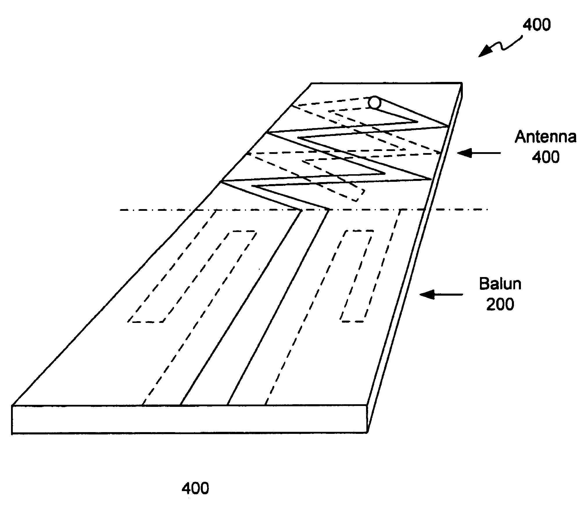
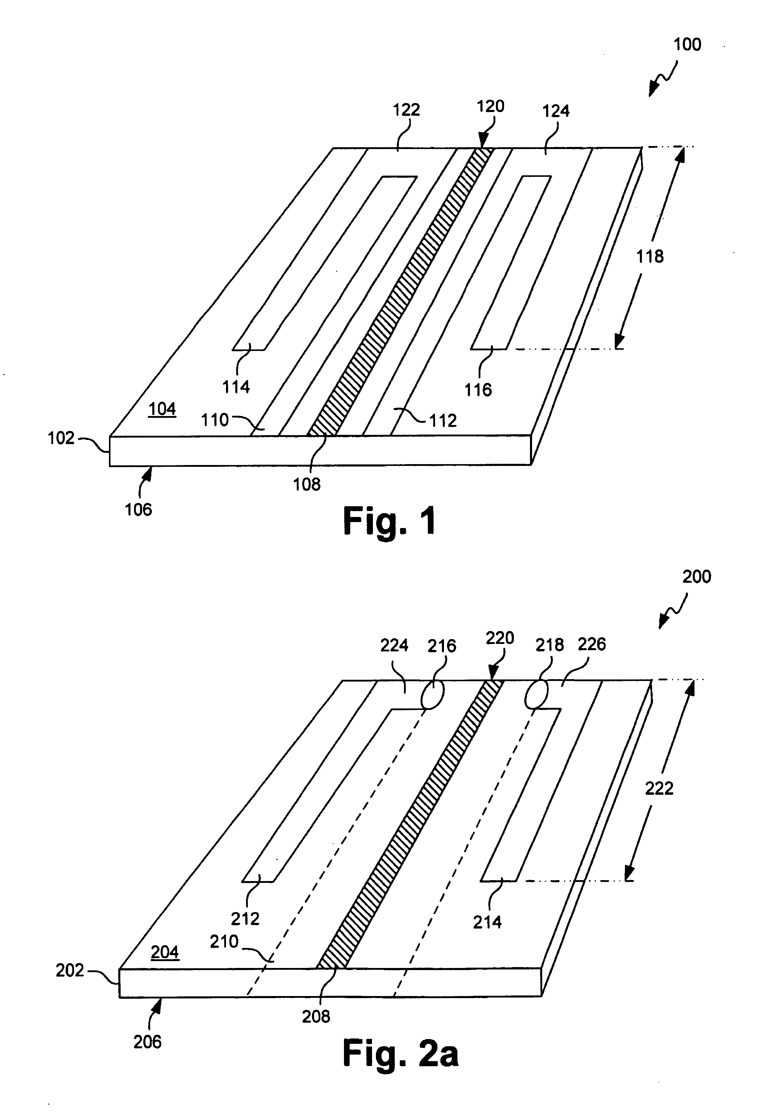
[0030]FIG. 1 is a perspective drawing of one aspect of the present invention planar balun. As explained in more detail below, the planar balun is connected to the transmission line interface of an unbalanced microstrip antenna (not shown is this figure). The combination of planar balun, with the unbalanced microstrip antenna, results in a balanced antenna. That is, the overall result is a balanced antenna, referred to herein as an effectively balanced dipole antenna that minimized transmission line radiation.

[0031]More specifically, FIG. 1 depicts a coplanar balun 100. The coplanar balun 100 includes a dielectric layer 102 with a first side 104 and a second side 106 that cannot be seen in this view. An unbalanced coplanar transmission line is shown, with a signal line 108 (cross-hatched lines) interposed between a pair of coplanar grounds 110 and 112, on the dielectric layer first side 104. A pair of planar stubs 114 and 116 is formed in the dielectric layer first side 104. Each stu...


PUM


Abstract

A effectively balanced dipole antenna is provided comprising an unbalanced microstrip antenna having a transmission line interface and a planar balun connected to the transmission line interface of the antenna. The balun can be coplanar or multi-planar. For example, a coplanar balun includes an unbalanced coplanar transmission line, with a signal line interposed between a pair of coplanar grounds, and a pair of planar stubs plan-wise adjacent the coplanar grounds. The coplanar grounds are connected to the plane stubs with conductive lines proximate to the antenna transmission line interface. A microstrip planar balun includes an unbalanced microstrip signal line, a microstrip ground formed on the dielectric layer underlying the signal line, and a pair of planar stubs, plan-wise adjacent the microstrip ground. The planar stubs can be located on the same dielectric layer as the signal line or the ground. A stripline planar balun is also provided.

Description

BACKGROUND OF THE INVENTION[0001]1. Field of the Invention[0002]This invention generally relates to wireless communication antennas and, more particularly, to an effectively balanced dipole, formed from an unbalanced microstrip antenna, and suitable for use in a wireless communications device telephone.[0003]2. Description of the Related Art[0004]The size of portable wireless communications devices, such as telephones, continues to shrink, even as more functionality is added. As a result, the designers must increase the performance of components or device subsystems while reducing their size, or placing these components in less desirable locations. One such critical component is the wireless communications antenna. This antenna may be connected to a telephone transceiver, for example, or a global positioning system (GPS) receiver.[0005]Wireless communications devices, a wireless telephone or laptop computer with a wireless transponder for example, are known to use simple cylindrical...

Claims


Application Information

Patent Timeline
Patent Type & Authority Patents(United States)
IPC IPC(8): H01Q1/38H01Q9/28
CPCH01Q9/285H01Q1/38
Inventor TRAN, ALLEN
Owner DRNC HLDG INC
Why Eureka
Try Eureka