
Electrophoretic display

a display and display technology, applied in the field of displays, can solve the problem of display content being on the display surface for a relatively long tim

Inactive Publication Date: 2006-01-17
E INK CORPORATION
View PDF17 Cites 116 Cited by
  • Summary
  • Abstract
  • Description
  • Claims
  • Application Information

AI Technical Summary

Benefits of technology

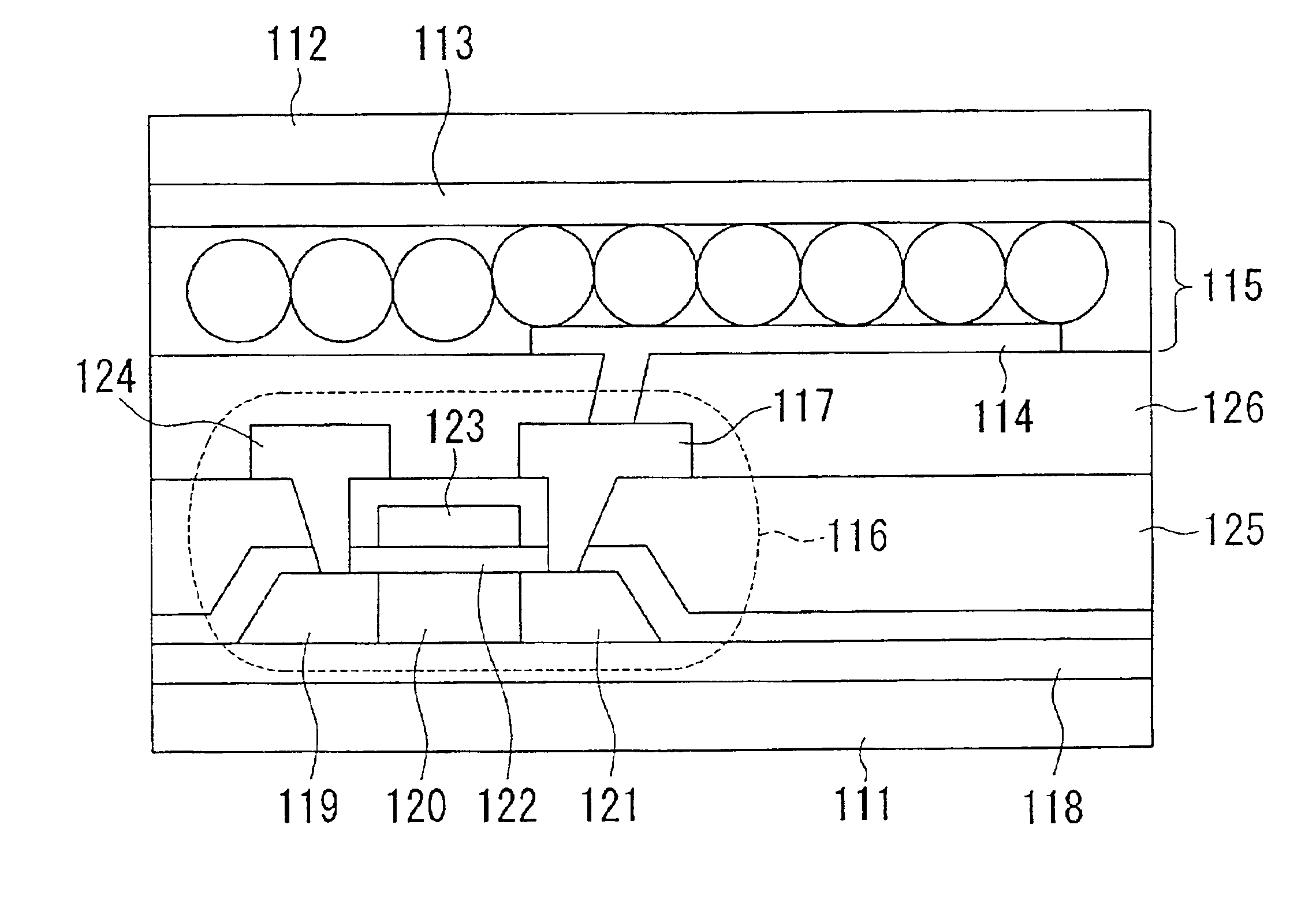
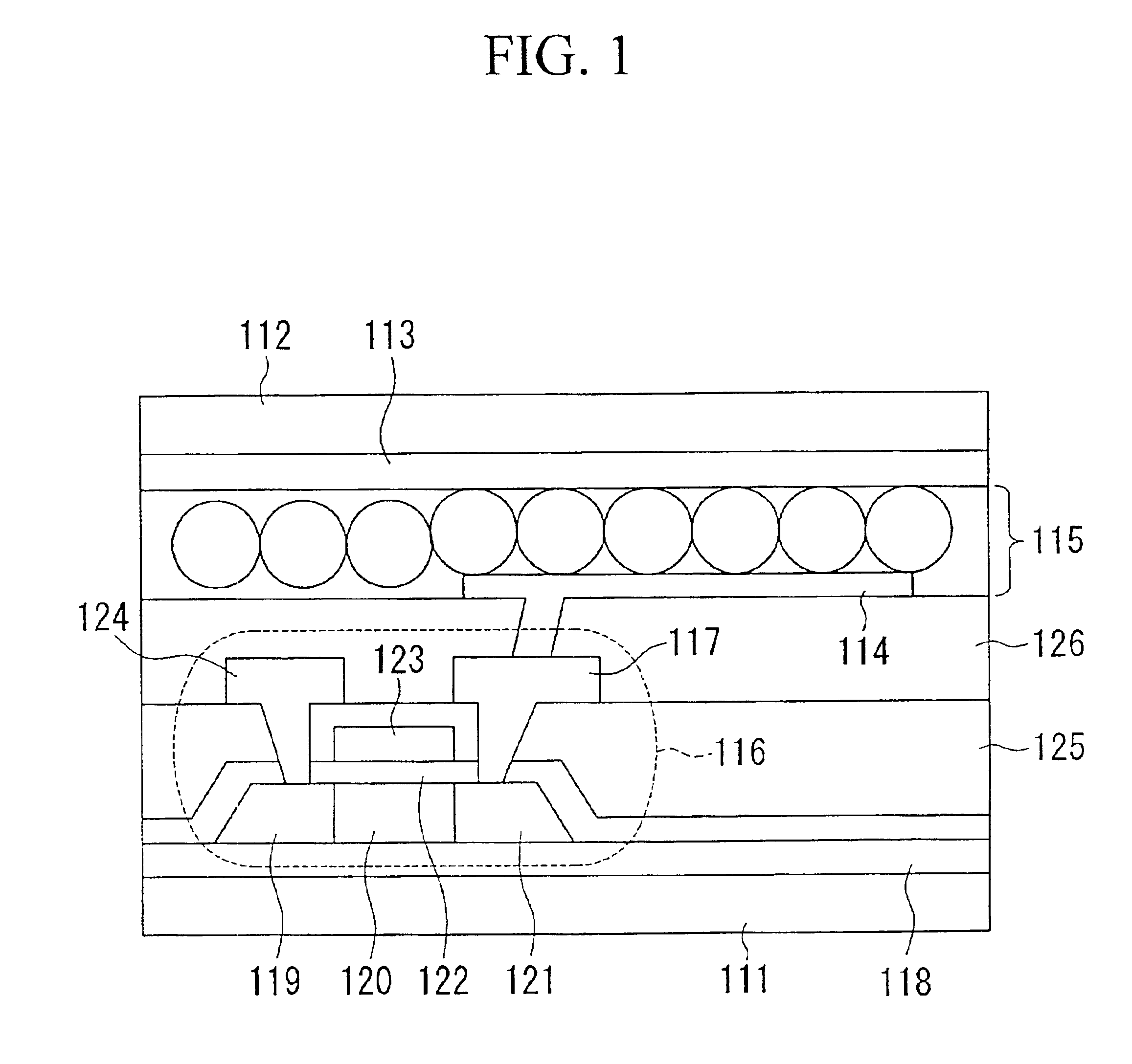
[0020]It is an object of the invention to provide an electrophoretic display of an active-matrix type that can be driven without error during rewriting of display contents for pixels, thus yielding highly reliable operation.
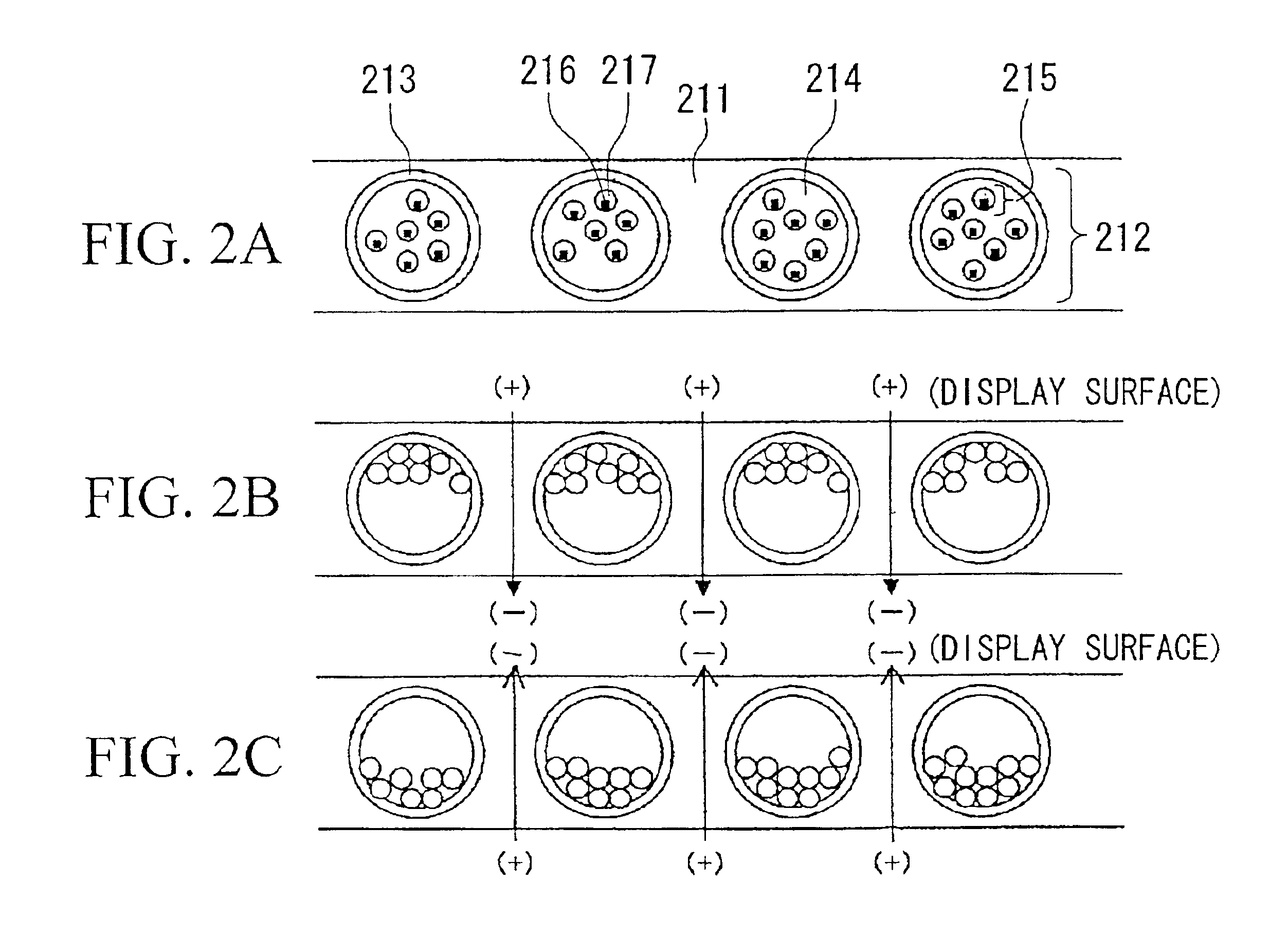
[0022]All the pixel electrodes are simultaneously set to the low electric potential while the common electrode is set to the high electric potential so that the display content is erased from the entire area of the display surface at once. In this case, the display surface is entirely white because the negatively charged particles move upwards within the microcapsules when attracted to the common electrode. Then, the pixel electrodes are driven respectively in response to display data while the common electrode is set to the low electric potential so that the display content is rewritten with a new one in response to the display data. Due to the aforementioned processes, it is possible to ensure rewriting of the display content without error.
[0023]Because the negatively charged particles and the liquid are both approximately set to the same specific gravity, the negatively charged particles can maintain their positions within the microcapsules after the electric field disappears. Hence, it is possible for the display content to remain on the display surface for a relatively long time.

Problems solved by technology

Hence, it is possible for the display content to remain on the display surface for a relatively long time.

Method used


Image

  • Electrophoretic display
  • Electrophoretic display
  • Electrophoretic display

Examples


Embodiment Construction

[0041]This invention will be described in further detail by way of examples with reference to the accompanying drawings.

[0042]An electrophoretic display of this invention can be applied to electronic books, an example of which is shown in FIG. 3. That is, FIG. 3 shows a brief appearance of an electronic book 31 employing the electrophoretic display of this invention. The electronic book 31 is basically constructed by a frame 32 and an open / close cover 33. A display 34 is installed in the frame 32 such that its display surface is exposed outside, and it is controlled by switches or buttons arranged in an area for operation controls 35. Inside of the frame 32, there are provided a controller 36, a counter 37 and a memory 38, which are shown in FIG. 4. The display 34 provides a pixel array portion 39 that is formed by filling thin-film elements with electrophoretic ink, and peripheral circuits 40 whose circuit elements are integrated. The pixel array portion 39 and its peripheral circu...


PUM


Abstract

An electrophoretic display using electrophoretic ink is configured by a transparent substrate, a common electrode, pixel electrodes, and thin-film transistors. An electrophoretic ink layer, which is arranged between the common electrode and pixel electrodes, is actualized by a linear arrangement of microcapsules each of which contains negatively charged white particles dispersed in a liquid having a specific color. All the pixel electrodes are simultaneously set to the low electric potential while the common electrode is set to the high electric potential so that the display content is erased from the entire area of the display surface at once, and then the pixel electrodes are driven respectively in response to display data while the common electrode is set to the low electric potential so that the display content is rewritten with a new one in response to the display data.

Description

BACKGROUND OF THE INVENTION[0001]1. Field of the Invention[0002]This invention relates to displays such as liquid crystal displays, and particularly to electrophoretic displays that display images using display media such as electrophoretic ink in accordance with electrophoretic effects.[0003]2. Description of the Related Art[0004]Conventionally, electrophoretic effects are well known among scientists and engineers, wherein charged particles dispersed in a fluid or liquid medium move under the influence of an electric field. As an example of the application of the electrophoretic effects, engineers try to realize displays by using charged pigment particles that are dispersed and contained in dyed solution arranged between a pair of electrodes. Under the influence of an electric field, the charged pigment particles are attracted to one of the electrodes, so that desired images will be displayed. The dyed solution in which charged pigment particles are dispersed is called electrophore...

Claims


Application Information

Patent Timeline
IPC IPC(8): G09G3/34G02B5/20G02F1/167G09G3/20
CPCG02F1/167G09G3/344G09G2300/08G09G2310/0245G09G2330/021G09G2310/0275G09G2310/04G09G2310/061G09G2310/063G09G2310/0267
Inventor INOUE, SATOSHI
Owner E INK CORPORATION
Features
  • Generate Ideas
  • Intellectual Property
  • Life Sciences
  • Materials
  • Tech Scout
  • Unparalleled Data Quality
  • Higher Quality Content
  • 60% Fewer Hallucinations
Learn More