
Device with thermoelectric cooling

a technology of thermoelectric cooling and devices, applied in the field of memory read heads, can solve the problems of limiting the increase of application current and inacceptable increases in and achieve the effects of increasing the output voltage, and reducing the operating temperature of devices

Active Publication Date: 2006-01-17
HEADWAY TECH INC
View PDF13 Cites 10 Cited by
  • Summary
  • Abstract
  • Description
  • Claims
  • Application Information

AI Technical Summary

Benefits of technology

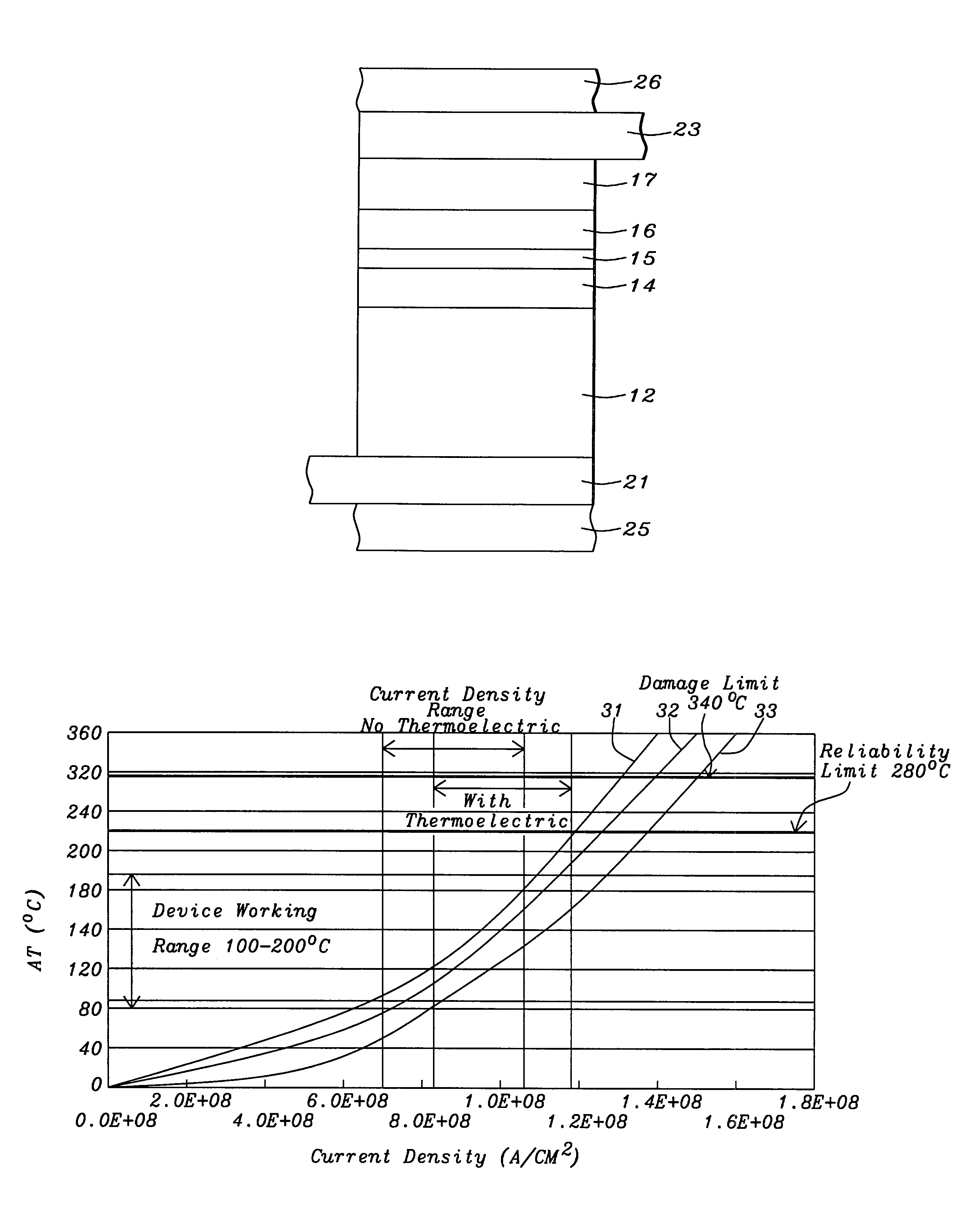
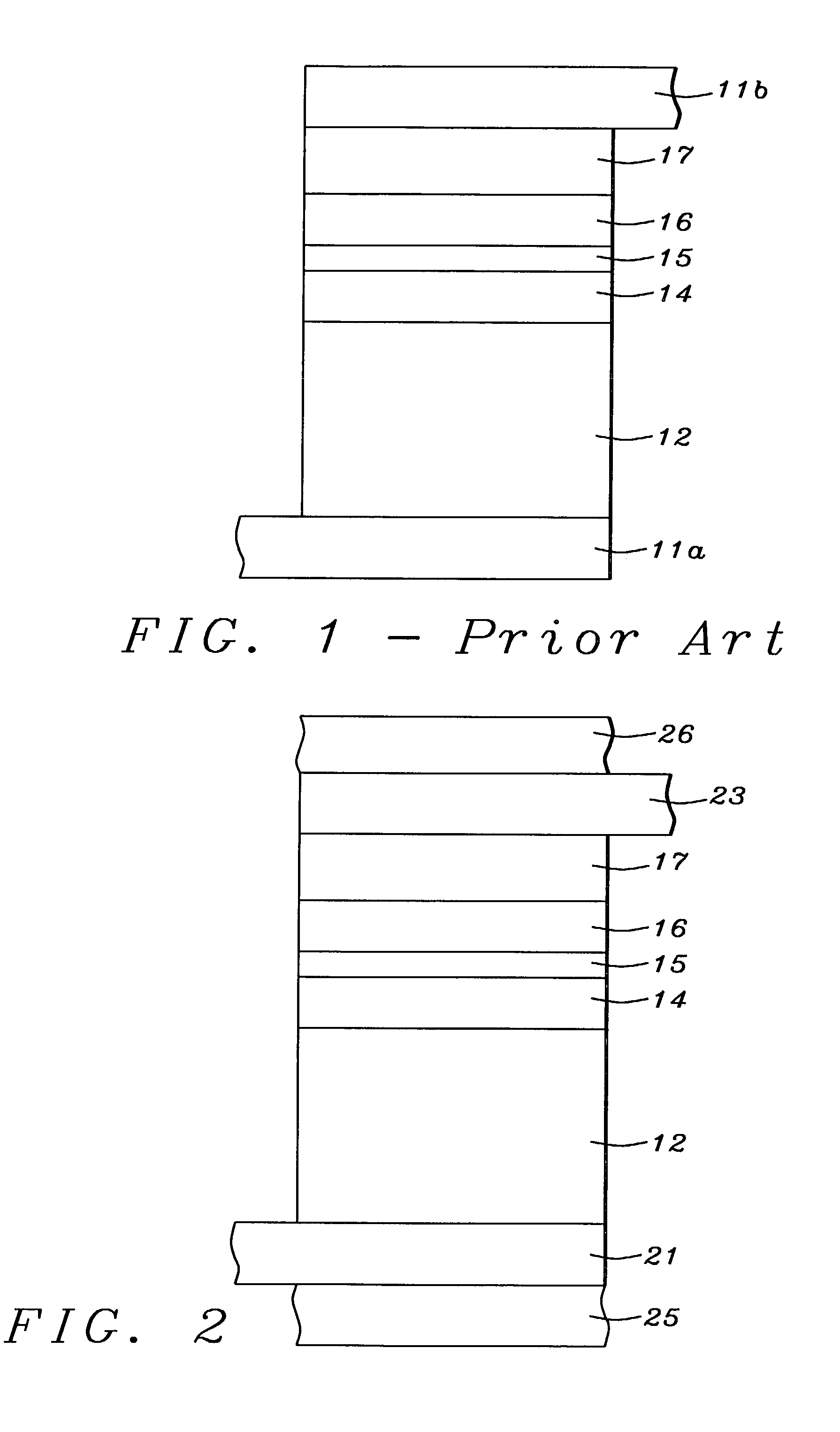
[0013]It has been an object of at least one embodiment of the present invention to incorporate thermoelectric cooling in a CPP device thereby increasing its current carrying capability.
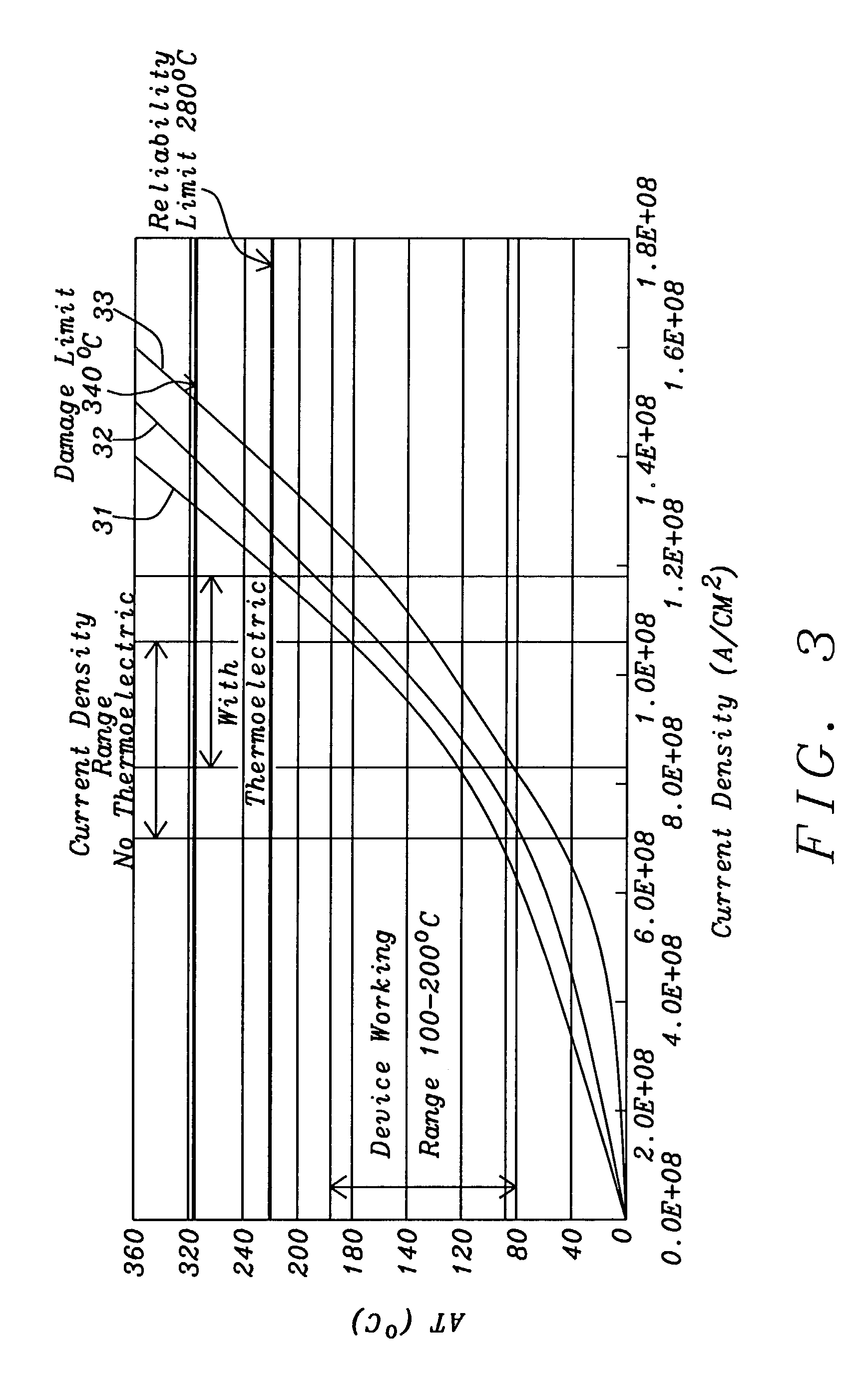
[0018]These objects have been achieved by using different materials for the upper and lower leads of the CPP device. More specifically, said materials are selected so that they differ significantly in their TEPs (thermoelectric powers). The result is that when DC is passed through the device hot and cold junctions are formed. Heat from the hot junction is removed by the substrate, resulting in a net local cooling of the device which enables it operate at higher power. For a GMR device, this translates to a larger output voltage, making the device easier, more sensitive, and more reliable to use.

Problems solved by technology

Almost all attempts by the prior art to increase Vout have focused on ways to increase DR since it has been assumed that I was already at its maximum value, any further increases being expected to lead to unacceptable increases in the operating temperature of the device.
To increase application current I is as challenging as to increase DR, especially when the device dimension is getting smaller.
Device damage from Joule heat will limit the increase of the application current.

Method used


Image

  • Device with thermoelectric cooling
  • Device with thermoelectric cooling
  • Device with thermoelectric cooling

Examples


Embodiment Construction

[0022]Thermoelectrics are based on the Peltier Effect, discovered in 1834, in which DC current, applied across two dissimilar materials, causes a temperature differential. The Peltier Effect is one of three thermoelectric effects, the other two being the Seebeck Effect and the Thomson Effect. The latter effect acts on a single conductor, the Peltier Effect is typically a junction phenomenon, while the Seebeck effect is responsible for the Peltier and Thomson effects in the absence of an applied voltage.

[0023]Thermoelectric modules are widely available and usually comprise two thin ceramic wafers with a series of P and N doped bismuth-telluride semiconductor material sandwiched between them. The N type material has an excess of electrons, while the P type material has a deficit of electrons. As the electrons move from the P type material to the N type material, the electrons must enter a higher energy state. The energy to achieve this is extracted from the surrounding lattice so the ...


PUM

PropertyMeasurementUnit
thicknessaaaaaaaaaa
thicknessaaaaaaaaaa
heat dissipationaaaaaaaaaa

Abstract

Increasing the output signal from CPP GMR devices by increasing the read current has not previously been considered an option because it would make the device run too hot. This problem has been overcome by using, for the upper and lower leads, materials that differ significantly in their thermoelectric powers. Thus, when DC is passed through the device, from − to + TEP leads, hot and cold junctions are formed and heat is transferred from the micro-device into the leads, resulting in a net local cooling of the device which enables it to operate at higher power. For a GMR device, this translates to a larger output voltage, making it easier, more sensitive, and more reliable to use.

Description

FIELD OF THE INVENTION[0001]The invention relates to the general field of device arrays, particularly memory read heads and most particularly CPP GMR devices with reference to allowing higher operating currents by providing very local cooling.BACKGROUND OF THE INVENTION[0002]Current perpendicular to plane, giant magneto-resistance (CPP, GMR) read heads are considered as promising candidates for 180 Gb / in2 and higher magnetic recording densities. This increase in recording density requires the reduction of the read head dimension. For example, for 180 Gb / in2, dimensions around 0.1×0.1 microns are required. A CPP read head can be considered functional only if a significant output voltage, Vout can be achieved when the head senses the magnetic field of a recorded medium. If DR is defined as the resistance change under the magnetic field for the head sensor and I is the current that is sent through the sensor, thenVout=DR×I  (Eq. 1)[0003]Almost all attempts by the prior art to increase ...

Claims


Application Information

Patent Timeline
Patent Type & Authority Patents(United States)
IPC IPC(8): G11B5/39H01L35/28F25D23/12F25B21/02H01L35/20H01L35/30H01L35/32H01L43/08
CPCB82Y10/00B82Y25/00H01L35/20G11B5/3912G11B5/3909G11B2005/3996H10N10/854
Inventor LIU, YUEJU, KOCHANCHANG, JEI-WEICHEN, JULIE
Owner HEADWAY TECH INC
Learn More