
Methods and apparatus for identification and imaging of specific materials

a technology of specific materials and methods, applied in the field of methods and apparatus for analyzing and/or imaging specific materials in objects under study, can solve the problems of non-compliance, non-compliance, shading, streaking,

Inactive Publication Date: 2006-01-17
GE MEDICAL SYST GLOBAL TECH CO LLC
View PDF19 Cites 55 Cited by
  • Summary
  • Abstract
  • Description
  • Claims
  • Application Information

AI Technical Summary

Benefits of technology

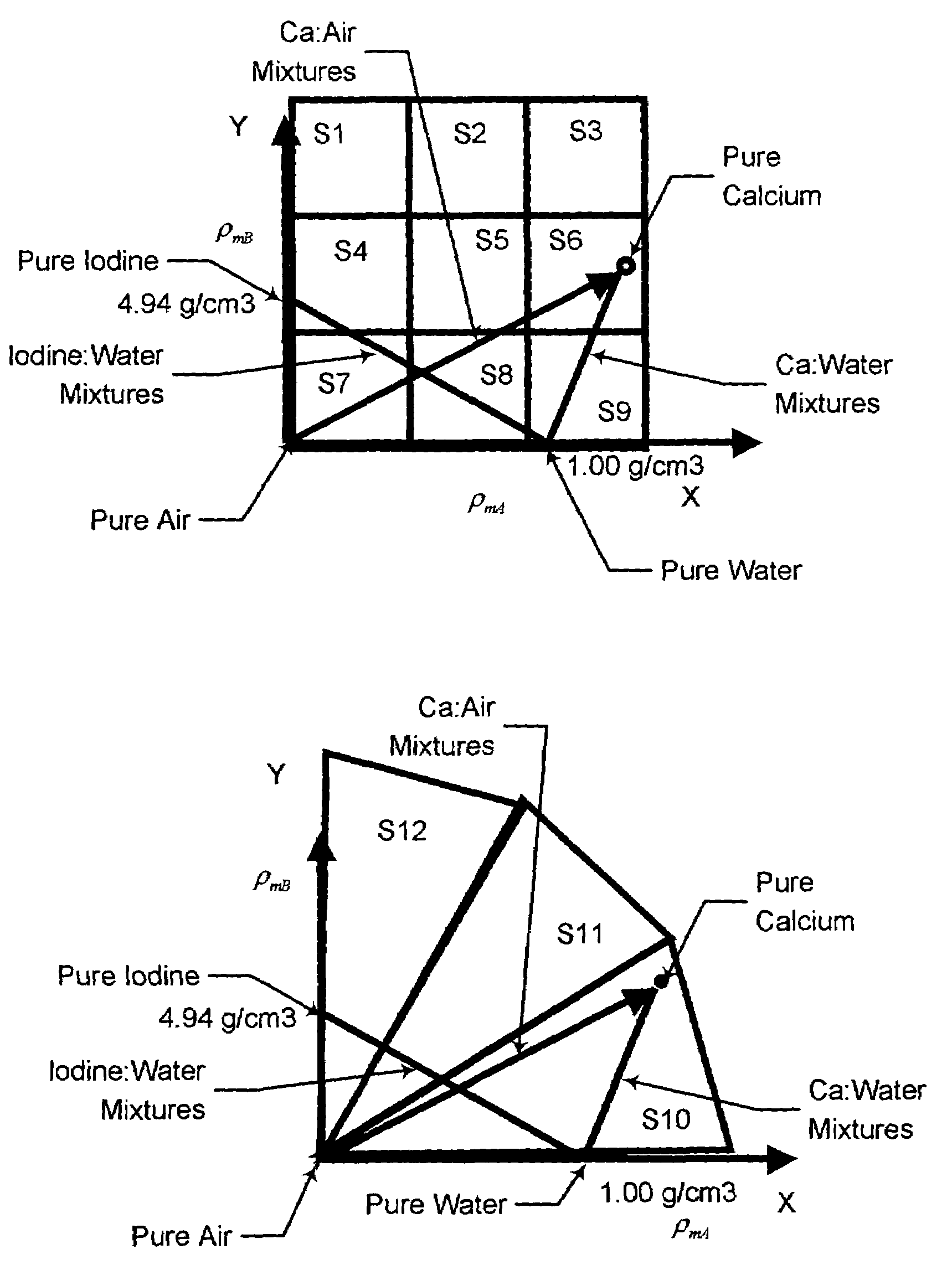
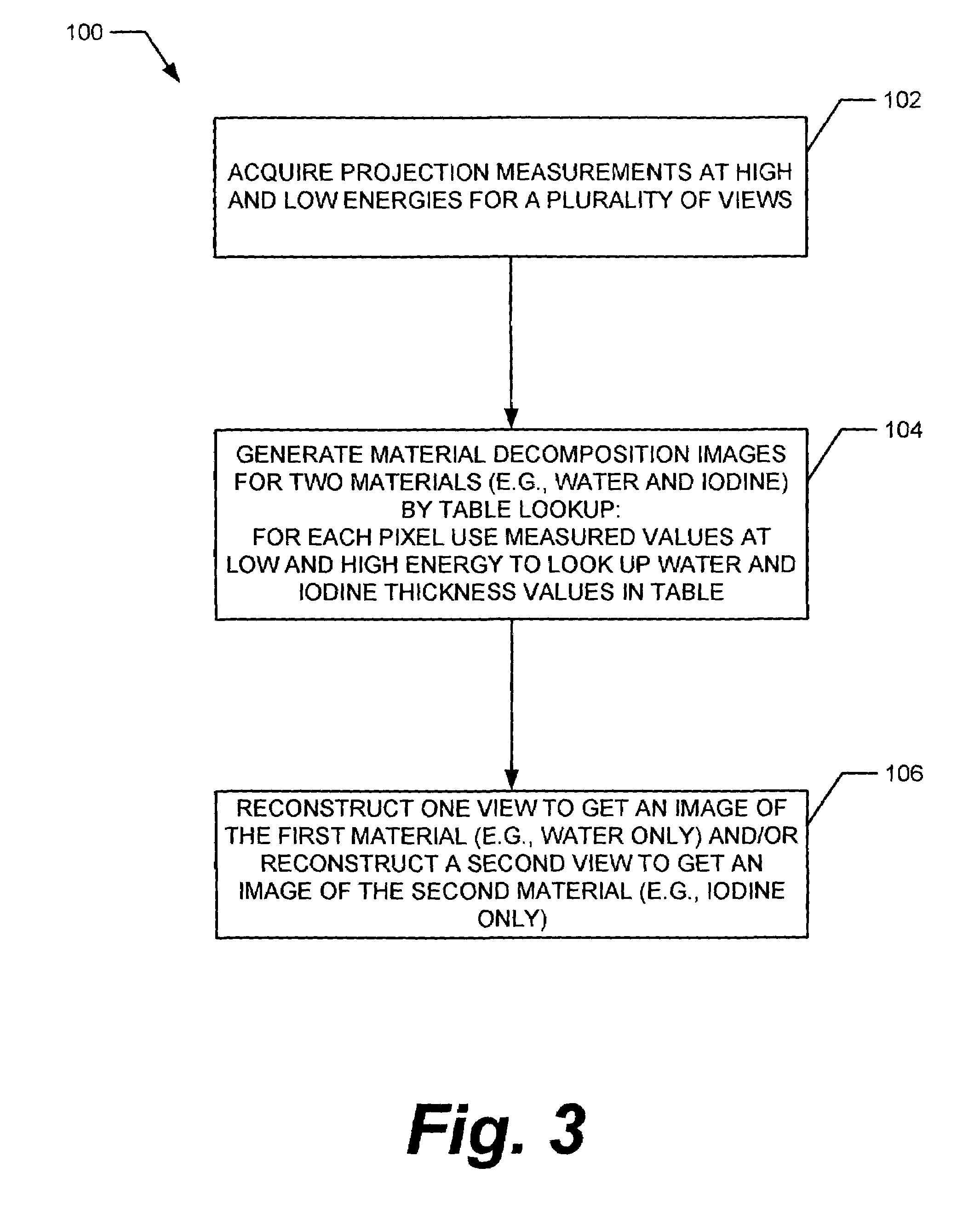
"The present invention provides a method for analyzing materials in an object by acquiring x-ray projection data of the object at high energy and at low energy for a plurality of views. The acquired data is utilized to determine material densities at each pixel for two selected basis materials, and a composition of the object is determined by mapping material density regions for the two selected basis materials. An image indicative of the composition of the object is displayed. The invention also provides an apparatus for analyzing materials in an object, including an x-ray source, a detector, a computer, a storage device, and a display. The apparatus is capable of providing quantitative material information and improving target material visibility and quantification accuracy."

Problems solved by technology

Because many known CT detection systems do not provide energy resolution, it is not possible to provide material characterization information for an object under study.
As a result, known computed tomographic (CT) images do not differentiate materials that have similar density but different atomic numbers, and images may look substantially uniform even though an object under study has variations in its material composition.
In addition, beam-hardening artifacts, such as non-uniformity, shading, and streaking can result from the non-linear relationship between x-ray attenuation and path lengths for polychromatic x-ray beams in CT imaging systems.
Also, known CT imaging systems do not provide quantitative image values.
This contamination reduces the visibility of the basis materials in the images, and also results in density errors in quantification applications.

Method used


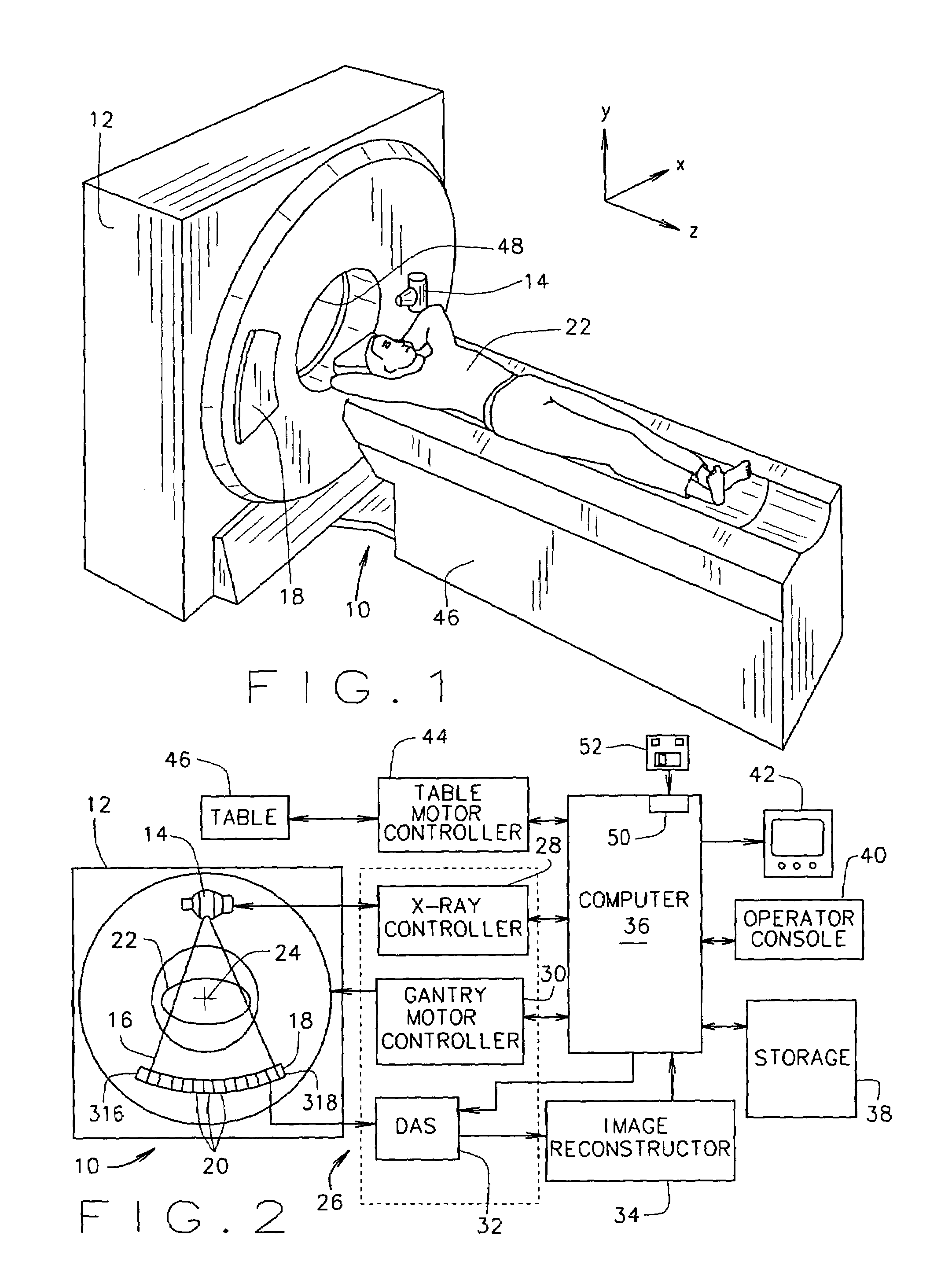
Image

  • Methods and apparatus for identification and imaging of specific materials
  • Methods and apparatus for identification and imaging of specific materials
  • Methods and apparatus for identification and imaging of specific materials

Examples


Embodiment Construction

[0022]Example embodiments of methods and apparatus for multiple material decomposition for energy discrimination are described below in more detail. A technical effect of the methods and apparatus described herein include at least one of facilitating the extraction of information concerning a object utilizing a CT imaging system, generation of images representative of a plurality of different materials contained within such an object, and automated identification of materials contained within an object.

[0023]In some known CT imaging system configurations, an x-ray source projects a fan-shaped beam which is collimated to lie within an X-Y plane of a Cartesian coordinate system and generally referred to as an “imaging plane”. The x-ray beam passes through an object being imaged, such as a patient. The beam, after being attenuated by the object, impinges upon an array of radiation detectors. The intensity of the attenuated radiation beam received at the detector array is dependent upon...


PUM

PropertyMeasurementUnit
energyaaaaaaaaaa
densitiesaaaaaaaaaa
densityaaaaaaaaaa

Abstract

A method for analyzing materials in an object includes acquiring x-ray projection data of the object at high energy and at low energy for a plurality of views. The acquired x-ray projection data is utilized in a material decomposition to determine material densities at each pixel for two selected basis materials. A composition of an object at each pixel is determined utilizing a determined mapping of material density regions for the two selected basis materials. An image indicative of the composition of the object is displayed utilizing the determined composition.

Description

BACKGROUND OF THE INVENTION[0001]This invention relates generally to methods and apparatus useful for determining the composition of materials under study, and more particularly to methods and apparatus for analyzing and / or imaging specific materials in objects under study.[0002]Because many known CT detection systems do not provide energy resolution, it is not possible to provide material characterization information for an object under study. For example, a highly attenuating material with low density can produce the same CT number in an image as a less attenuating material with high density. As a result, known computed tomographic (CT) images do not differentiate materials that have similar density but different atomic numbers, and images may look substantially uniform even though an object under study has variations in its material composition. In addition, beam-hardening artifacts, such as non-uniformity, shading, and streaking can result from the non-linear relationship betwee...

Claims


Application Information

Patent Timeline
Patent Type & Authority Patents(United States)
IPC IPC(8): G01N23/087A61B6/00A61B6/03H05G1/64
CPCA61B6/032A61B6/4035A61B6/583A61B6/482A61B6/405
Inventor DU, YANFENGTKACZYK, JOHN ERIC
Owner GE MEDICAL SYST GLOBAL TECH CO LLC
Learn More