
Time of flight mass spectrometer and multiple detector therefor

Inactive Publication Date: 2005-09-06
THERMO FINNIGAN
View PDF25 Cites 43 Cited by
  • Summary
  • Abstract
  • Description
  • Claims
  • Application Information

AI Technical Summary

Benefits of technology

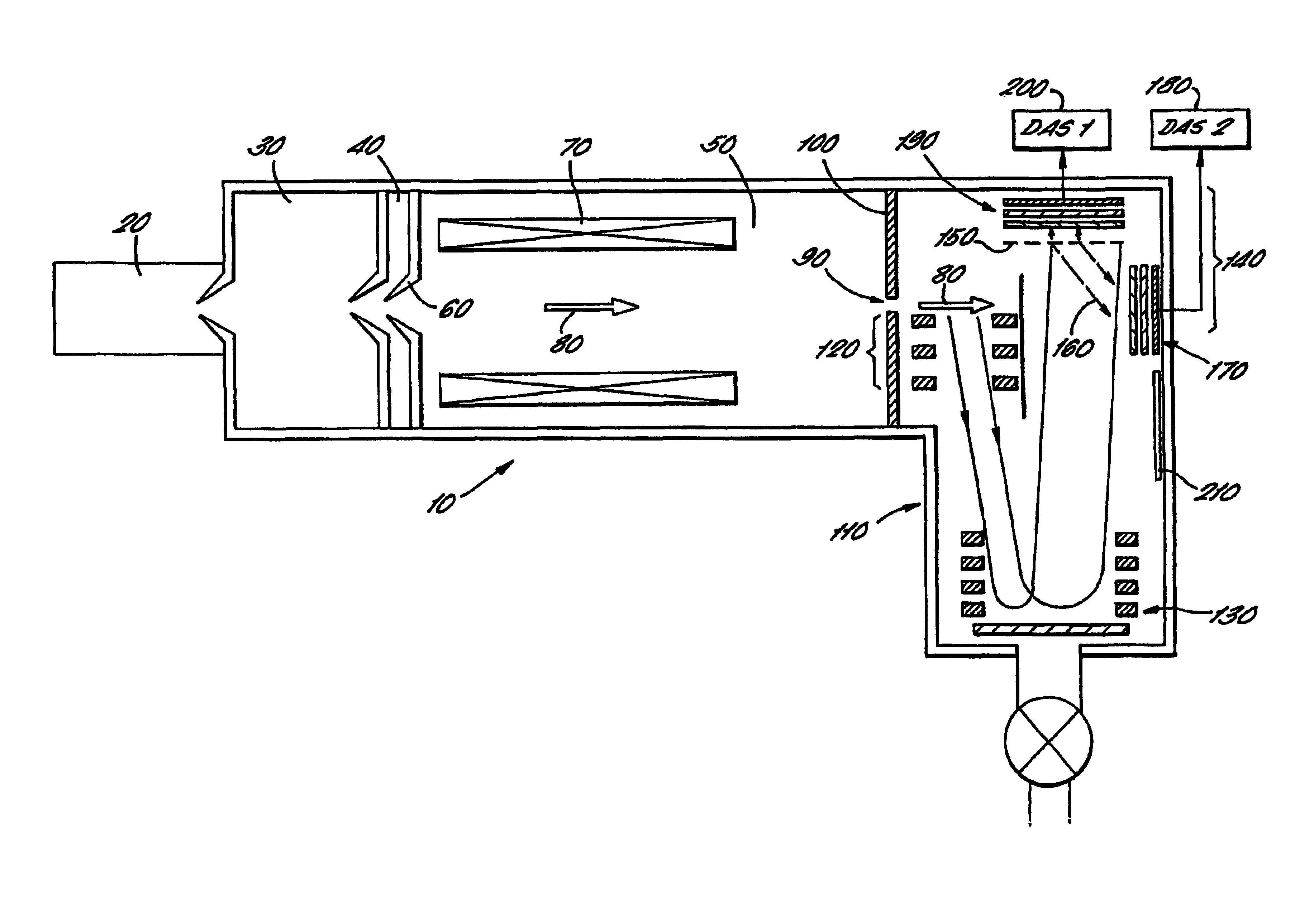
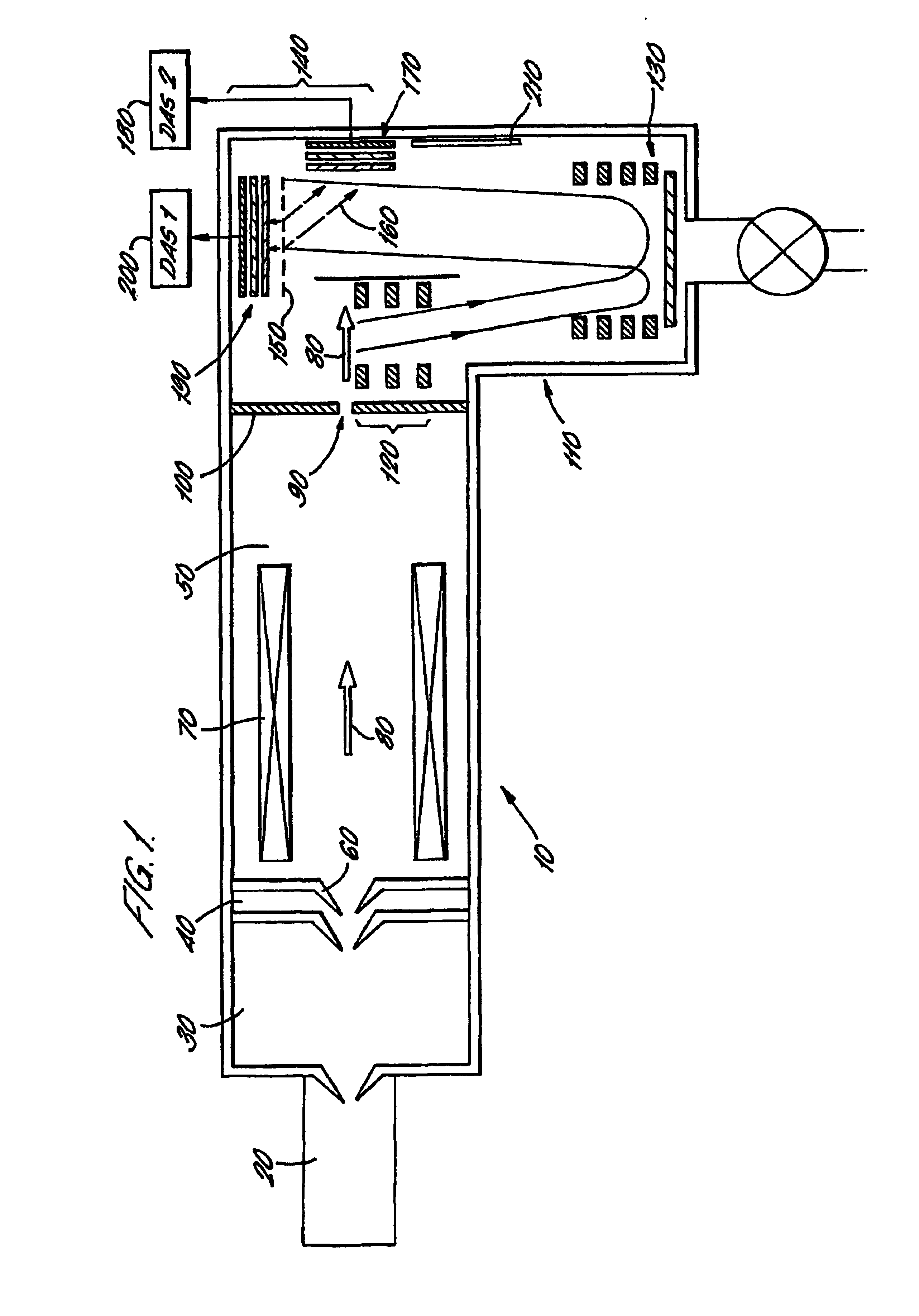
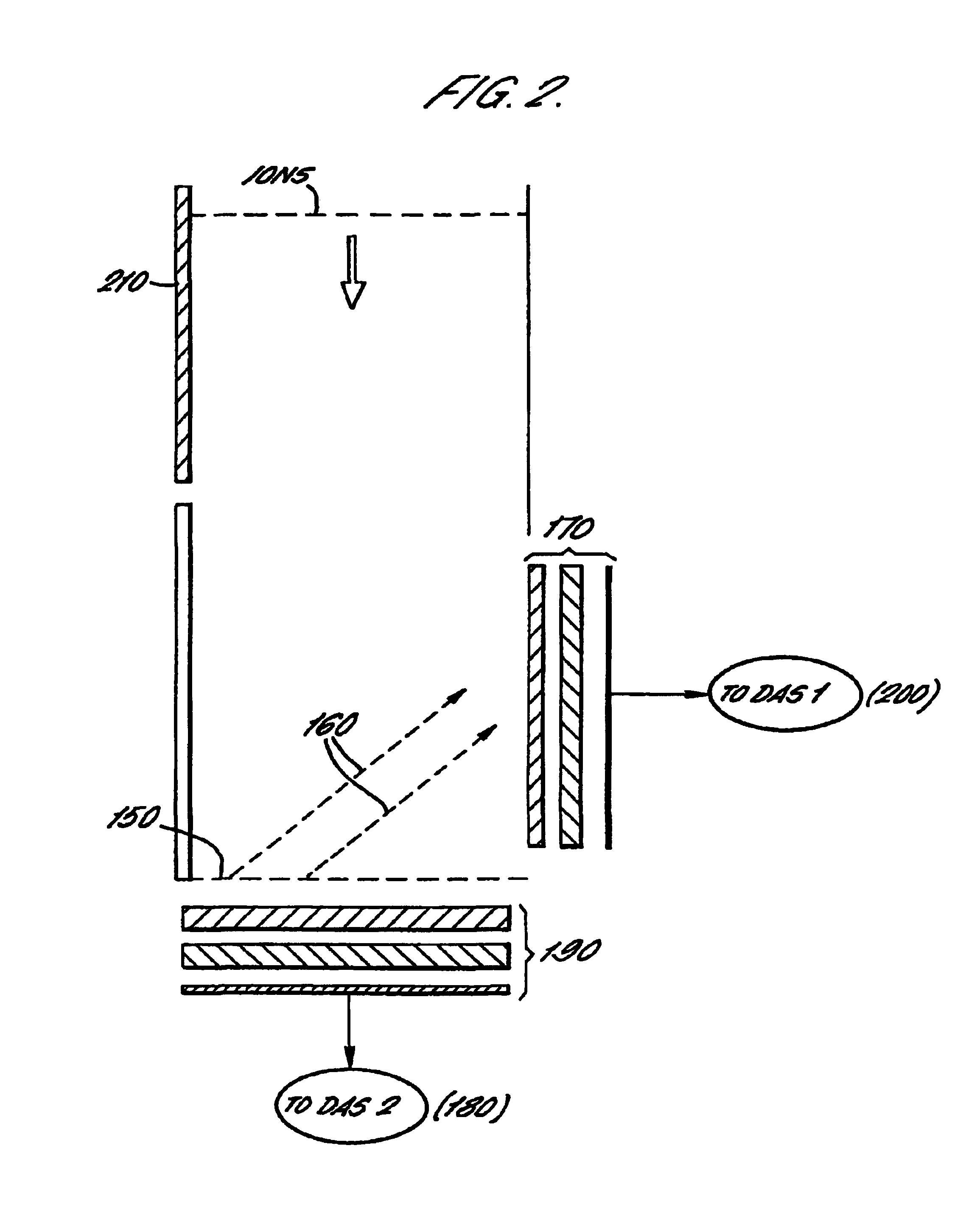
[0018]The detector of the invention accordingly provides a multiple detector wherein ions that have passed through a TOFMS enter into the detector arrangement through a common entrance window and are then divided by an ion beam splitter such as a conversion dynode or grid. Those ions striking the ion beam splitter generate, in the preferred embodiment, secondary electrons which are detected by a first detector means, whereas those ions passing through the ion beam splitter are detected by a second detector means. The ions are accordingly divided at an early stage in their detection, and the multiple detector arrangement accordingly provides greatly reduced electronic and physical cross-talk between the detectors. The dynamic range is extended without sacrifice of linearity, and better quantitation is available.
[0020]It is preferable that the ion beam is divided into two unequal parts so that one of the detectors continues to operate even when the other is saturated. In preferred embodiments, greater than 90% of the ion beam is allowed to pass through the ion beam splitter which may be, for example, a grid or mesh. Alternatively, less than 10% of the ion beam may pass through the ion beam splitter so that more than 90% is intercepted by it. The latter arrangement is particularly preferred because it is easier to manufacture than a largely transparent grid. Also, the latter arrangement allows secondary electrons which may be generated when the ion beam strikes the beam splitter to be focussed in time of flight as they pass towards the first detector means. Electrons are typically easier to focus than incoming ions because electrons are relatively much lighter and faster than ions so that TOF spreading is correspondingly smaller.

Problems solved by technology

One of the primary challenges in TOFMS is to maximize the dynamic range of the device.
Although ADC data acquisition systems do not suffer from the drawbacks of time to digital converters (TDC) (see below), their dynamic range is limited by the non-linearity of the electron multiplier and also by the speed of the ADC itself.
Even a fast ADC (<5 ns sampling rate), forming a first part of a transient recorder, has a limited dynamic range, and becomes complex, expensive and problematic at the highest mass accuracies demanded.
Also, signal variations on the ADC reduce the mass accuracy of the mass spectrometer.
There is, however, a limit to the dynamic range of a TDC detector, caused by a so-called dead time associated with ion detection.
However, the problems characteristic of ADC detectors identified above still remain at higher ion concentrations.
This technique also suffers from the problems associated with a combined TDC / ADC system.
The problem with this, of course, is that increases in the number of detectors increases the cost and, on average, an array of N detectors can only increase the total number of ions detected by a maximum of N times.
Such multiple detector techniques suffer from drawbacks, nevertheless.
Firstly, physical cross-talk between the channels is inevitable.
In addition, the close proximity of the anodes causes capacitive coupling between each which in turn increases the likelihood of electronic cross-talk.
This results in reduced sensitivity for subsequent mass peaks.
This problem is particularly pronounced in narrow ion beams such as are produced in orthogonal acceleration TOFMS.
Whilst the solution provided by U.S. Pat. No. 5,777,326 does largely remove the mass dependence upon the ratio of anode areas, it fails to address the other problems with this multiple detector arrangement and also extends dynamic range only by a factor equal to the number of channels.
Thus, the construction can become complex and even then may not be adequate for certain applications such as gas chromatography / mass spectrometry (GC / MS).

Method used


Image

  • Time of flight mass spectrometer and multiple detector therefor
  • Time of flight mass spectrometer and multiple detector therefor
  • Time of flight mass spectrometer and multiple detector therefor

Examples


Embodiment Construction

[0031]FIG. 1 shows, in schematic terms, a time-of-flight mass spectrometer (TOFMS) 10. The TOFMS comprises an ion source shown as a representative block 20 in FIG. 1. The ion source may be any suitable continuous or pulsed source, such as an electrospray source, an electron impact source or the like. Indeed, the ion source 20 may in fact be an upstream stage in an ms / ms analysis, e.g. a quadrupole mass spectrometer or an ion trap.

[0032]Gaseous particles from the ion source 20 enter an extraction chamber 30 which is evacuated to a first pressure below atmospheric pressure by a vacuum pump (not shown). The ions exit the extraction chamber 30 into an intermediate chamber 40 which is likewise evacuated, but to a lower pressure than the pressure within the extraction chamber 30, by a second vacuum pump, again not shown. The ions then leave the intermediate chamber 40 and enter a focussing chamber 50 through a conical inlet aperture 60. The focussing chamber 50 contains a series of rods 7...


PUM


Abstract

An ion detection arrangement 140 for a time-of-flight (TOF) mass spectrometer 10 includes a beam splitter formed as a mesh 150 at the end of the TOF acceleration and detection chamber 110. Ions enter the detection arrangement through a common entrance window and are then divided by the beam splitter. Those ions striking the mesh 150 generate secondary electrons 160 which are detected by a microchannel plate forming a first detector 170. Those ions passing through the ion beam splitter are detected directly by a second detector 190 also formed from a microchannel plate.The two detectors are each connected to a corresponding data acquisition system 180, 200 and the data obtained by each are combined to generate a mass spectrum. The problems of detector saturation are thus avoided.

Description

FIELD OF THE INVENTION[0001]The invention relates to a time of flight mass spectrometer (TOFMS) and in particular to a detector arrangement having a plurality of detectors for TOFMS.BACKGROUND OF THE INVENTION[0002]Time of flight mass spectrometry (TOFMS) allows the rapid generation of wide range mass spectra. TOFMS is based upon the principle that ions of different mass to charge ratios travel at different velocities such that a bunch of ions accelerated to a specific kinetic energy separates out over a defined distance according to the mass to charge ratio. By detecting the time of arrival of ions at the end of the defined distance, a mass spectrum can be built up.[0003]Most TOFMS operate in so-called cyclic mode, in which successive bunches of ions are accelerated to a kinetic energy, separated in flight according to their mass to charge ratios, and then detected. The complete time spectrum in each cycle is detected and the results added to a histogram.[0004]One of the primary ch...

Claims


Application Information

Patent Timeline
IPC IPC(8): H01J49/34H01J49/40
CPCH01J49/025H01J49/40
Inventor MAKAROV, ALEXANDER ALEKSEEVICHDAVIS, STEPHEN CHARLESSTRESAU, RICHARD WHITNEYHUNTER, KEVIN LIONELSHEILS, WAYNE LESLIE
Owner THERMO FINNIGAN
Learn More