Data transmit/receive device and data transmit/receive method

a data transmit/receive device and data technology, applied in the field of data transmit/receive device and data transmit/receive method, can solve the problems of inability to suitably reproduce the received data, inability to correctly decrypt encrypted data, and complex topology information production process, so as to facilitate the reception of original data, less processing, and less storage capacity

Inactive Publication Date: 2006-01-17
PANASONIC CORP
View PDF4 Cites 12 Cited by
  • Summary
  • Abstract
  • Description
  • Claims
  • Application Information

AI Technical Summary

Benefits of technology

[0028]Here, the receiving device can judge and recognize the original transmitting device correctly, simply by comparing the device-specific information before and after a bus reset, so that compared to a judgment and recognition based on Self ID packets as in the prior art, the reception of the original data can be continued easier, with less processing, and with much less storage capacity than in the prior art.

Problems solved by technology

This is because there are no other devices transmitting data.
As a result, even though the video deck receives encrypted data from the second TV set, it cannot correctly decrypt these encrypted data, because it has not obtained the encryption key for these data.
As a result, the video deck cannot suitably reproduce the received data.
However, with this conventional method, the topology information is produced based on the Self ID packets, which include the node information and the port status, so that the process for producing the topology information is very complex, and its load on the system is high.
In particular as the number of devices connected to the IEEE1394 bus and the number of physical ports increases, more time is needed to produce the topology information, and also for the comparison of the topology information, more time is needed for the judgment which devices have been newly connected to or disconnected from the bus, as the topology configuration becomes more complex.
If the real-time audio / video data received by a TV set or the like has been received by the receiving device, this audio / video data has to be recorded by the receiving device in real-time without loss, so that it is a serious problem when the time needed to again recognize that the TV set or the like is the transmitting device is too long.
Furthermore, considering the case that 63 devices are connected to the bus, then about 10 kbyte are needed for the calculation of the pattern of the topology, about 20 kbyte are needed for the topology information production process, and 8 to 252 byte are needed for the buffer 603, so that there is the problem that it is necessary to use a large storage capacity.

Method used


Image

  • Data transmit/receive device and data transmit/receive method
  • Data transmit/receive device and data transmit/receive method
  • Data transmit/receive device and data transmit/receive method

Examples


first embodiment

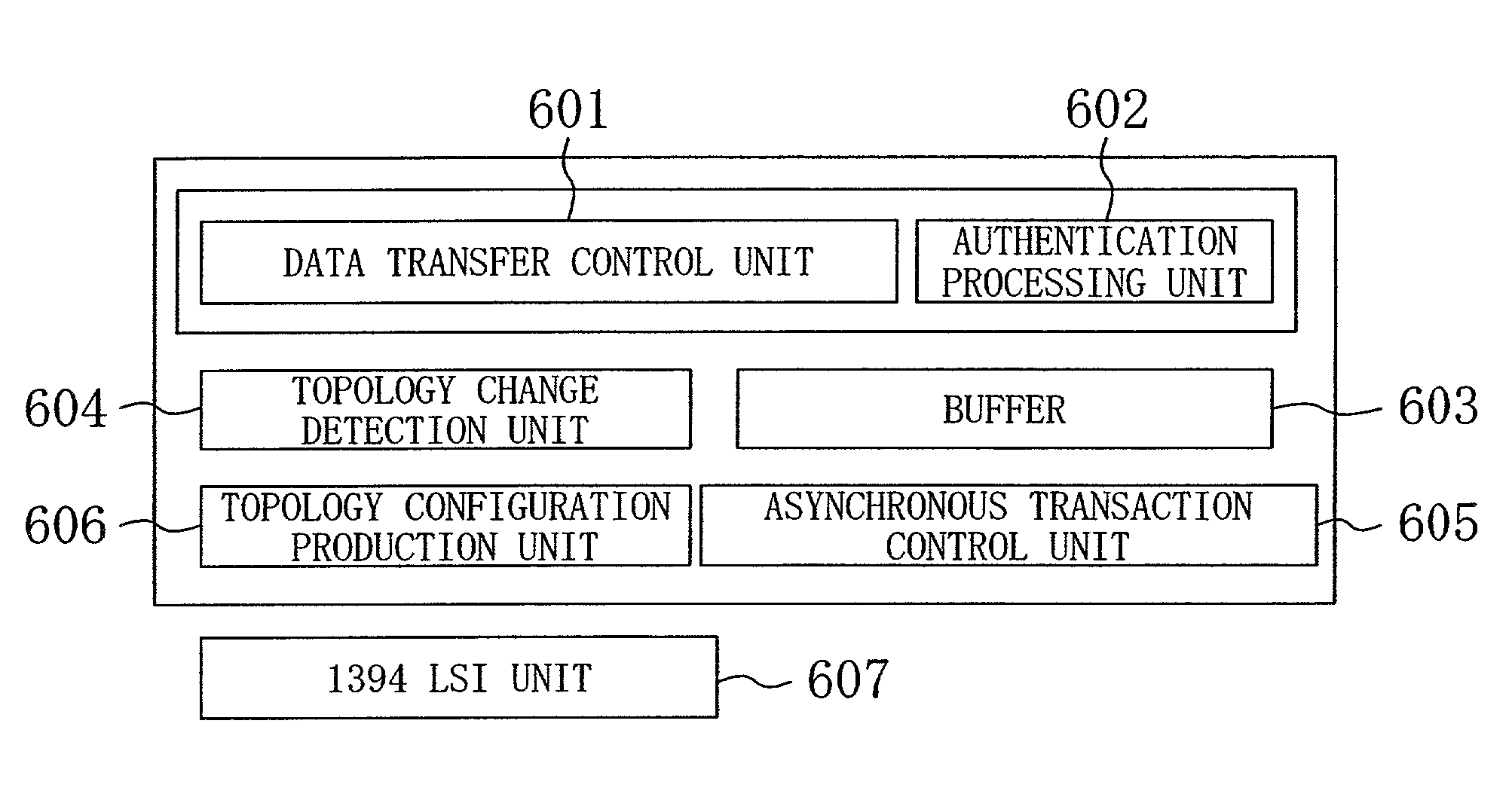
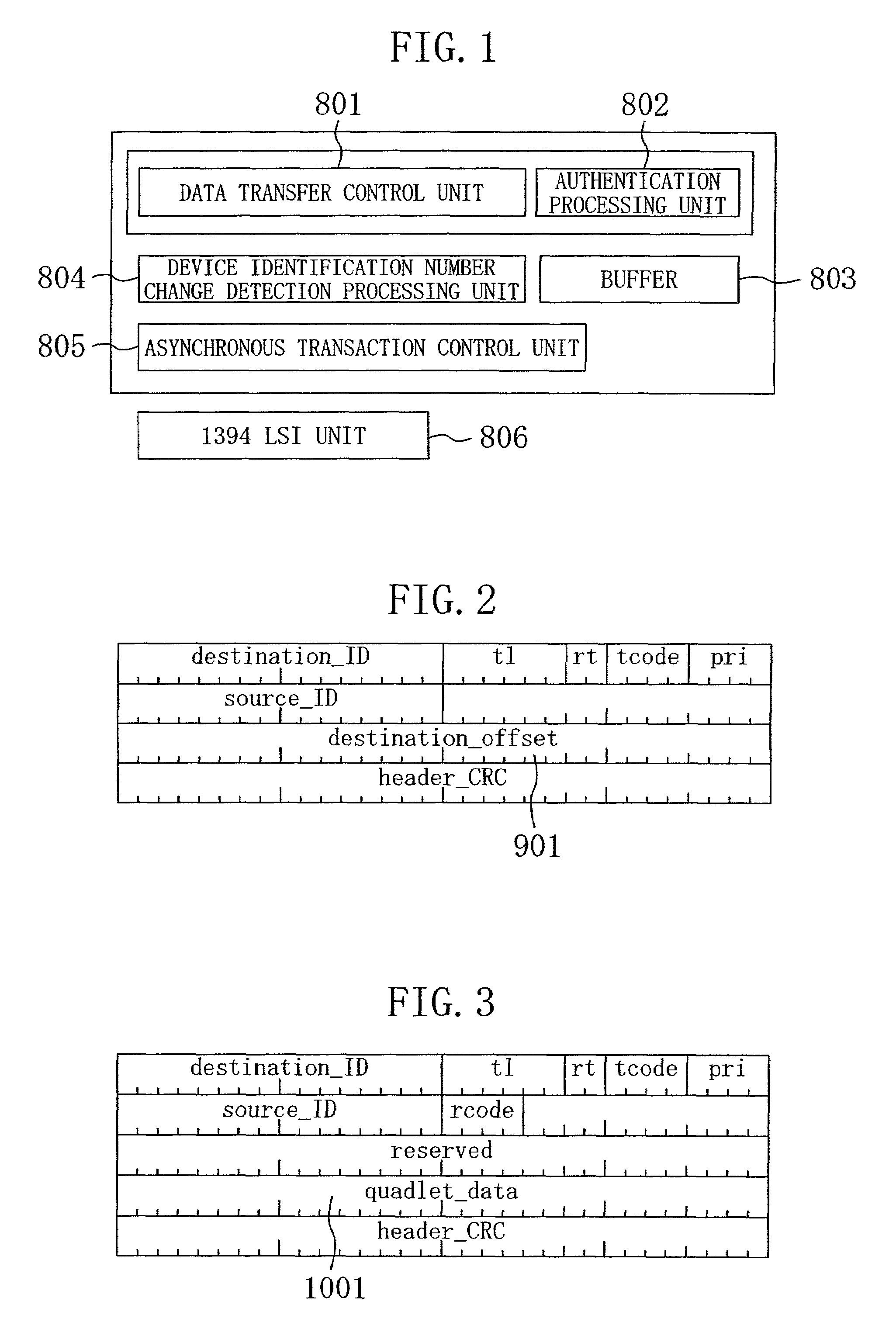
[0044]FIG. 1 shows the overall configuration of a data transmit / receive device of the first embodiment. In FIG. 1, numeral 806 denotes a 1394 LSI unit for transmitting / receiving packet data over a 1394 bus. Numeral 805 denotes an asynchronous transaction control unit for controlling communication using asynchronous packets. Numeral 804 denotes a device identification number change detection processing unit, which requests device-specific numbers as device-specific information, and based on the obtained device-specific numbers, detects changes in the transmitting device that is the communication partner of the receiving device, before and after a bus reset. Numeral 803 denotes a buffer for holding device-specific information that is necessary for the detection of changes of the transmitting device that is the communication partner. Numeral 801 denotes a data transfer control unit for controlling the transfer of data. Numeral 802 denotes an authentication processing unit for device au...

second embodiment

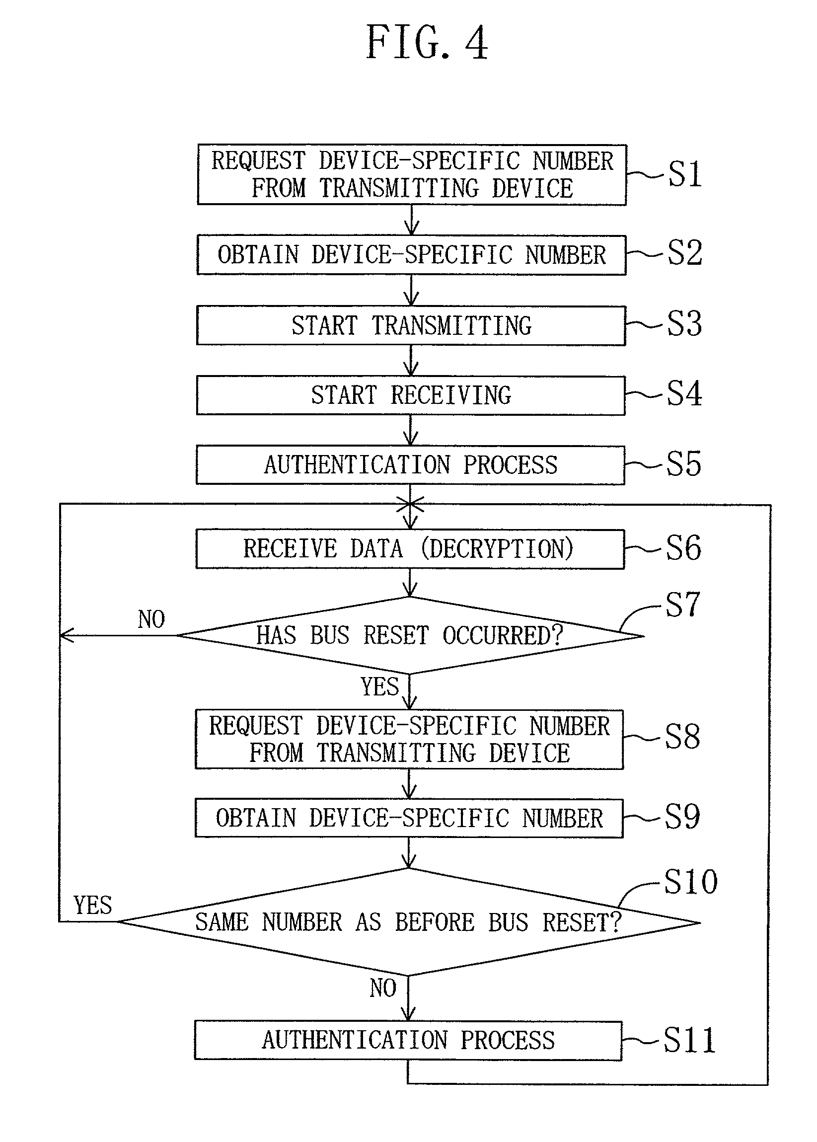
[0053]The following is an explanation of a second embodiment of the present invention. This embodiment is considered the best mode for carrying out the present invention. The overall configuration of the data transmit / receive device of this embodiment is the same as in FIG. 1, so that further illustrations and explanations have been omitted. However, the operation of this embodiment is different from that of the first embodiment. The following explains the data transmit / receive method of this embodiment, with reference to the flowchart in FIG. 6.

[0054]In Steps S1 and S2 of FIG. 6, the device-specific numbers of the devices are read in (function for reading device-specific numbers). That is to say, before the receiving device starts to receive asynchronous packet data from a transmitting device that is transmitting data on the channel that the receiving device wants to receive, in Step S1 the receiving device requests the device-specific number from the transmitting device with the q...

third embodiment

[0065]The following is an explanation of the third embodiment. This embodiment illustrates a case where the data from the transmitting device are not encrypted.

[0066]FIG. 9 is a flowchart showing the data transmit / receive method of this embodiment. The overall configuration of the data transmit / receive device of this embodiment is the same as in FIG. 1, so that further illustrations and explanations have been omitted. The flowchart in FIG. 9 is basically the same as the flowchart of the second embodiment shown in FIG. 6, but the authentication processes of Step S5 and Step S25 of FIG. 6 have been omitted. The rest of the data transmit / receive method is the same as in the second embodiment, so that further explanations of the flowchart in FIG. 9 have been omitted.

[0067]Explaining the data transmit / receive method of this embodiment with FIG. 7 and FIG. 8, if a TV set B is connected to the bus 10 while the video deck A receives unencrypted data from the TV set A on a channel with the n...


PUM


Abstract

In a data transmit/receive method for plurality of devices connected by a 1394 bus, a receiving device obtains a device-specific number of a transmitting device when starting to receive data. When a bus reset occurs, the receiving device again obtains the device-specific number from the transmitting device, and checks whether the device-specific numbers before and after the bus reset match. If the device-specific numbers differ, the receiving device obtains the device-specific number from all devices connected to the bus. If a device with the same device-specific numbers as prior to the bus reset is present among the obtained device-specific numbers, the channel number of the bus used for the transmitting of data is determined, and the receiving device starts receiving with that channel number. Then device authentication with the transmitting device is carried out, and key information for solving the encryption is obtained.

Description

BACKGROUND OF THE INVENTION[0001]The present invention relates to a data transmit / receive device and a data transmit / receive method for transmitting / receiving digital data between a transmitting device and a receiving device.[0002]Among conventional data transfer methods, there are methods using the IEEE1394 standard (IEEE: The Institute of Electrical and Electronic Engineers, Inc.) for example (see “IEEE1394 High Performance Serial Bus”). For data transfer with this IEEE1394 standard, there is isochronous communication, which is suitable for the transfer of synchronous data such as video signals or audio signals, and asynchronous communication, which is suitable for the transfer of non-synchronous data such as control signals, and both types of communication can be mixed on an IEEE1394 bus. Isochronous communication is so-called broadcasting-type communication, in which isochronous packets that a device on an IEEE1394 bus gives out can be received by all devices on that bus. By con...

Claims


Application Information

Patent Timeline
Patent Type & Authority Patents(United States)
IPC IPC(8): G06F17/00G06F13/38H04L12/28H04L12/40H04L12/64H04L29/06
CPCH04L12/2805H04L12/40052H04L12/40078H04N21/43632H04L12/40117H04L12/6418H04L63/0428H04L12/40104H04L12/2803H04L63/08
Inventor IWAMOTO, KIYOTAKA
Owner PANASONIC CORP
Why Eureka
Try Eureka