
Method of transforming variable loops into constant loops

Inactive Publication Date: 2006-01-17
ORACLE INT CORP +1
View PDF12 Cites 16 Cited by
  • Summary
  • Abstract
  • Description
  • Claims
  • Application Information

AI Technical Summary

Benefits of technology

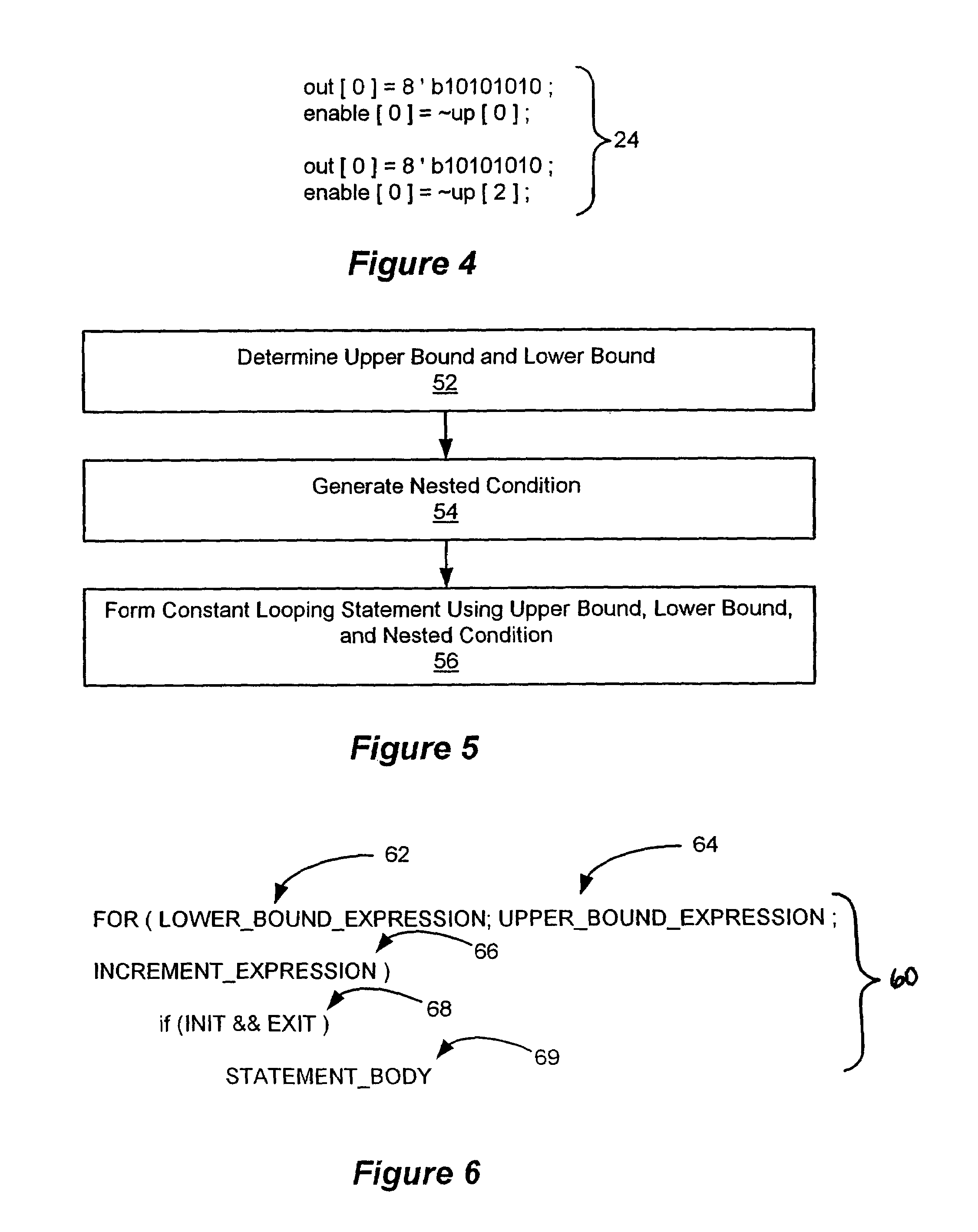
[0014]The constant looping statement formed by the disclosed system and method includes a loop index that varies between the upper bound and lower bound derived from the variable looping statement. The generated constant looping statement further includes a nested control statement, such as an “if” statement, which predicates execution of the body of the constant looping statement on a condition being satisfied. The condition checked within the nested control statement logically verifies that any conditions indicated by the initial expression and / or exit expression of the variable looping statement are met. Accordingly, while the generated upper and lower bounds may cause the loop index to assume values outside the range of values it would have taken on during execution of the original variable looping statement, the body of the generated constant looping statement is executed only in the event that conditions in both the initial expression and exit expression of the variable looping statement are satisfied. This advantageously allows use of upper and lower bounds in the generated constant looping statement that are not strictly “tight” without causing incorrect execution. In other words, the lower bound may be lower than the lowest possible loop index value in the variable looping statement, and the upper bound may be higher than the highest possible loop index value in the variable looping statement, without causing an incorrect loop index value to be applied to the body of the generated constant looping statement. The generated constant looping statement may then be unrolled in order to enable the various optimizations afforded by loop unrolling, such as increased parallelism during execution.
[0015]In an illustrative embodiment, the disclosed system is applicable to systems for processing HDL, such as HDL compilers. Since HDL models often are used to represent digital circuit designs, variables used within HDL programs typically represent lines or interfaces for electronically conveying binary logic signals between hardware components. Such interfaces may be individual lines, or groups of lines as in a data bus. Accordingly, variables used within an HDL model are often defined as “bit field” types of variables, within which each “bit” may take on the value 0 or 1, representing the state of an individual line or signal. The range of values bit field variables may take on is relatively limited, in comparison with the ranges of potential values for other types of variables. Due to the prevalence of bit field variables within HDL models, the initial expression and exit expression of variable looping statements in such models often involve comparison of the loop index with bit field variables. As a result, the determination of an upper and lower bound for a loop index may be based on the absolute ranges of the variables involved, without the risk of highly inefficient results. Moreover, the nested conditional statement employed by the disclosed system within the generated constant looping statement limits the number of unnecessary statements performed as a result of using bounds that are beyond the actual range of loop index values applied to the loop body. For these reasons, the disclosed system effectively provides a reasonably efficient technique for providing the benefits of loop unrolling to variable looping statements contained within programs such as programs written in an HDL.

Problems solved by technology

As a result, the determination of an upper and lower bound for a loop index may be based on the absolute ranges of the variables involved, without the risk of highly inefficient results.

Method used


Image

  • Method of transforming variable loops into constant loops
  • Method of transforming variable loops into constant loops
  • Method of transforming variable loops into constant loops

Examples


Embodiment Construction

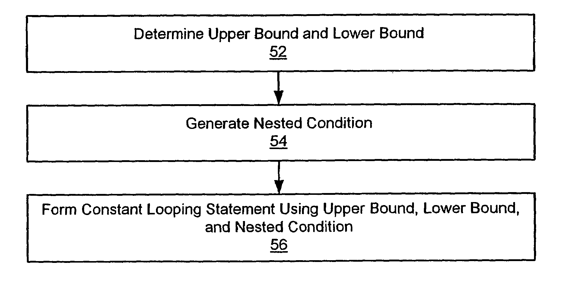
[0026]As shown in FIG. 5, in an illustrative embodiment, a series of steps are performed in order to process a variable looping statement such that the variable looping statement is transformed into a constant looping statement on which loop unrolling may be performed. The steps illustrated in FIG. 5 may be embodied within any specific type of computer program stored on a computer readable medium, and capable of execution on one or more processors within a computer system. For example, an executable program operable to perform the steps shown in FIG. 5 may be stored within a computer memory or program storage device that is communicably coupled to one or more processors operable to execute the computer program.

[0027]At step 52, the disclosed system determines an upper bound and a lower bound to be used to define a range of values for a loop index in a generated constant looping statement. The disclosed system determines the upper bound and lower bound at step 52 such that the range ...


PUM


Abstract

A system and method for processing a variable looping statement into a constant looping statement to enable loop unrolling. A lower bound and an upper bound of the loop index within the variable looping statement are determined. A constant looping statement is then formed using the lower bound and upper bound to define a range over which the loop index varies within the constant looping statement. The constant looping statement further includes a conditional statement that reflects conditions in the initial expression and / or the exit expression of the variable looping statement. The conditional statement controls execution of the body of the generated constant looping statement, which includes the body from the original variable looping statement. Loop unrolling may then be performed on the generated constant looping statement.

Description

CROSS REFERENCE TO RELATED APPLICATIONS[0001]N / ASTATEMENT REGARDING FEDERALLY SPONSORED RESEARCH OR DEVELOPMENT[0002]N / ABACKGROUND OF THE INVENTION[0003]The present invention relates generally to optimization of computer programs written in Hardware Description Languages (HDLs), and more specifically to a method of transforming variable loops into constant loops.[0004]In modern circuit design, particularly in the development of ASICs (Application Specific Integrated Circuits) and FPGAs (Field Programmable Gate Arrays), extensive use is made of models written using HDLs. Examples of tools for processing HDLs in use today include DesignCompiler™ of Synopsis, Inc., and DesignVerifier™ of Chrysalis. Examples of HDLs in use today include Verilog and VHDL (Very high speed integrated circuits HDL). In a typical design process, a hardware designer writes an HDL program representing the high level operation and / or design of a circuit. This HDL program may then be compiled and executed in ord...

Claims


Application Information

Patent Timeline
IPC IPC(8): G06F9/45
CPCG06F8/4441
Inventor LAM, WILLIAM K.ALLISON, DAVID S.
Owner ORACLE INT CORP
Learn More